Slideshows
PACE Spacecraft
List View »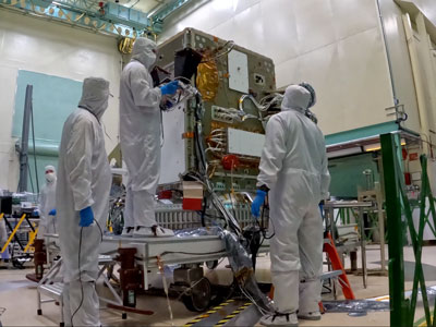
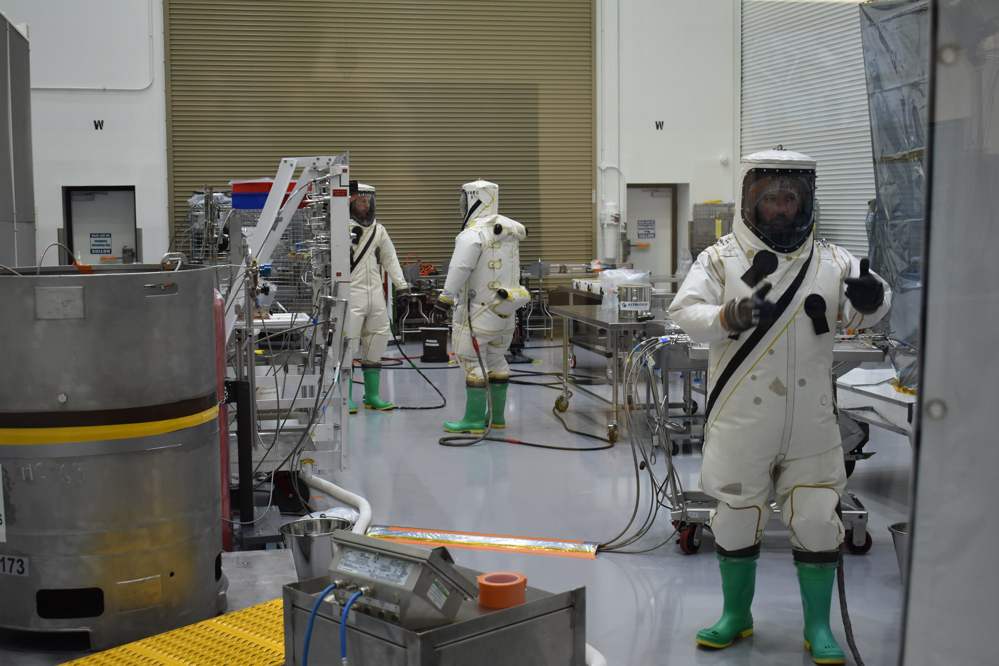
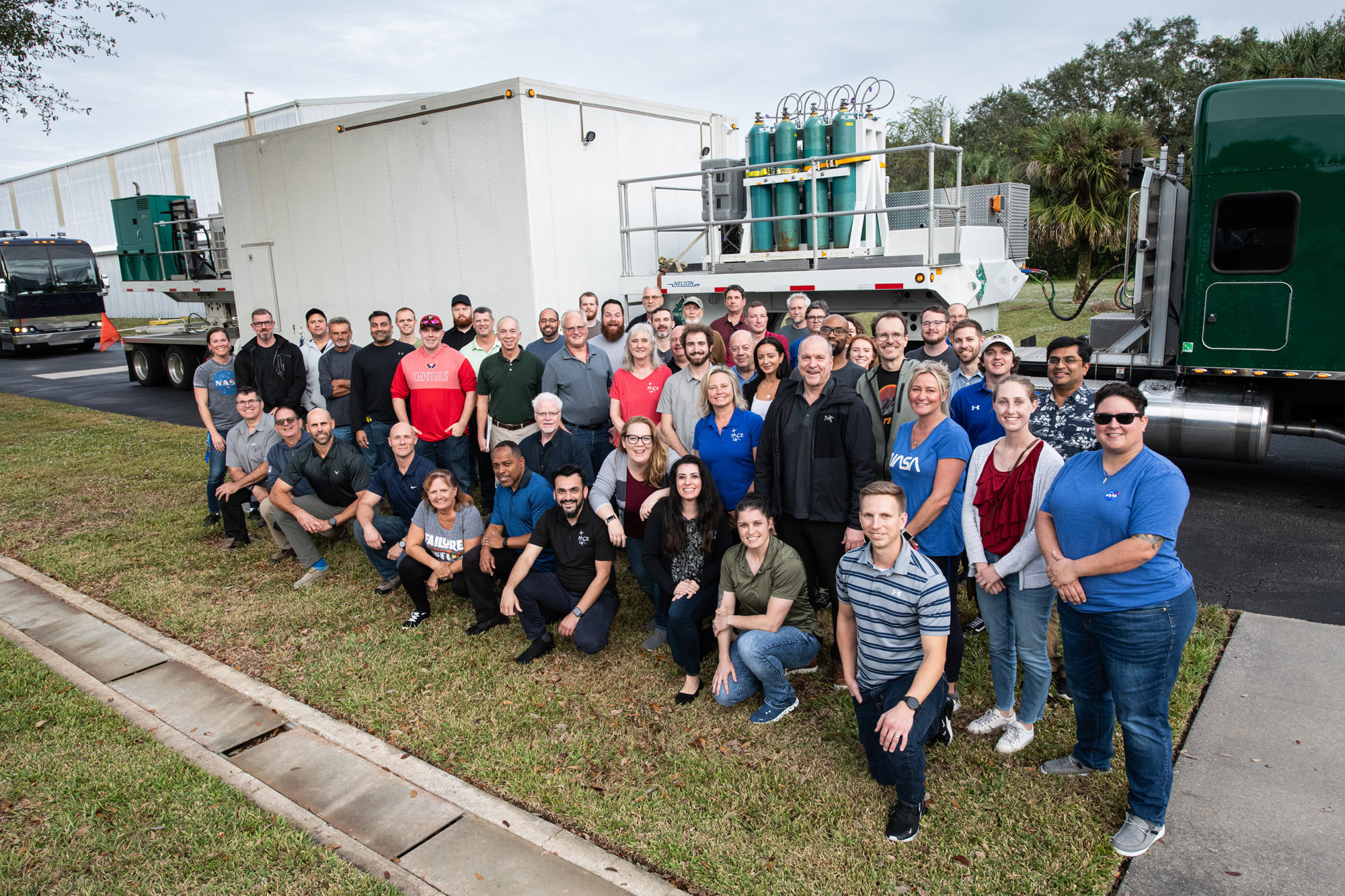
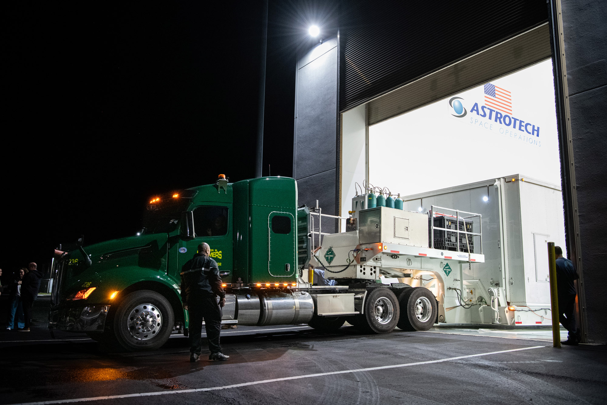
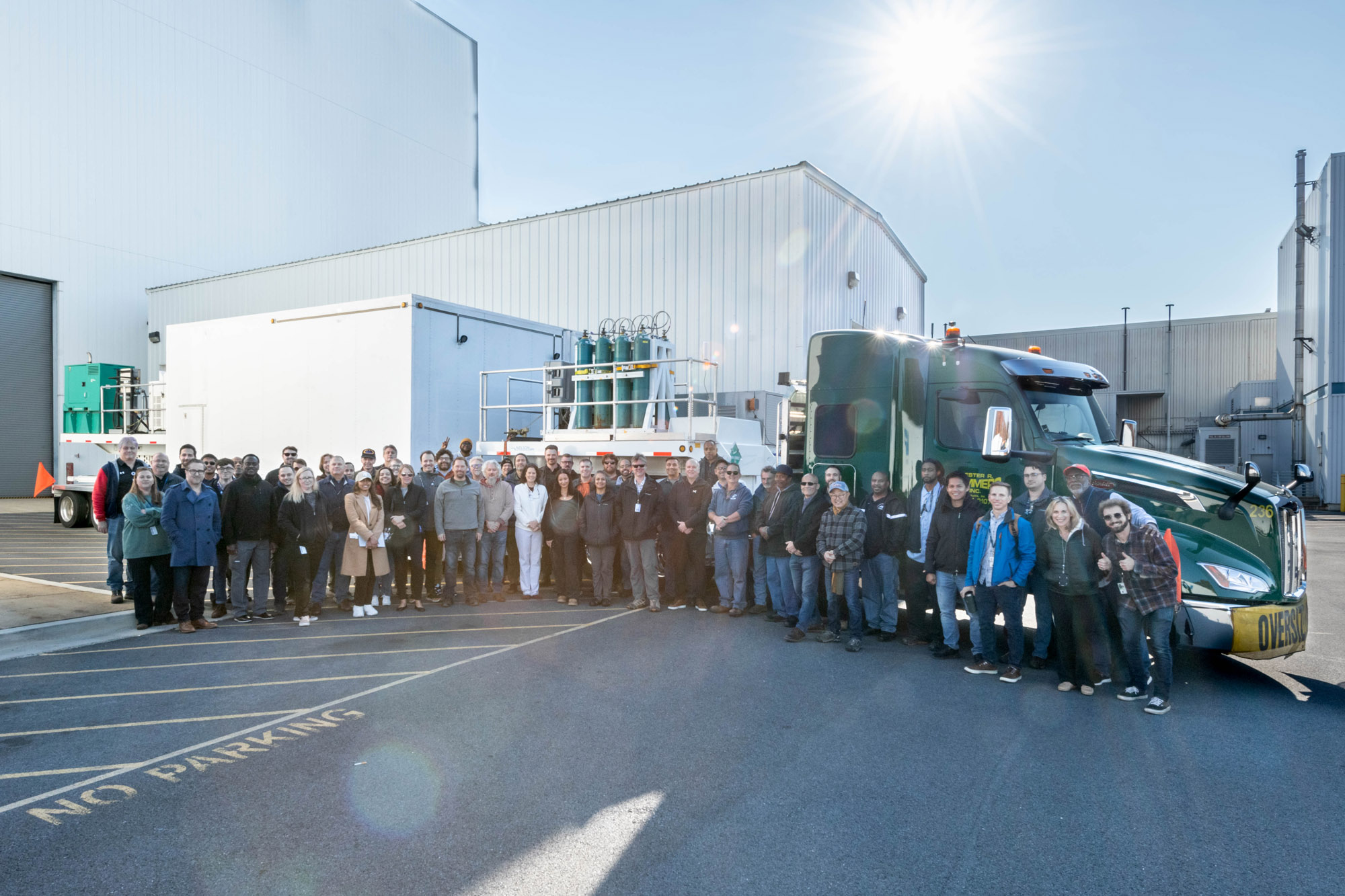
PACE Propellant Loading and Pressurization Procedure at Astrotech (Red Tag/Green Tag). Credit: NASA
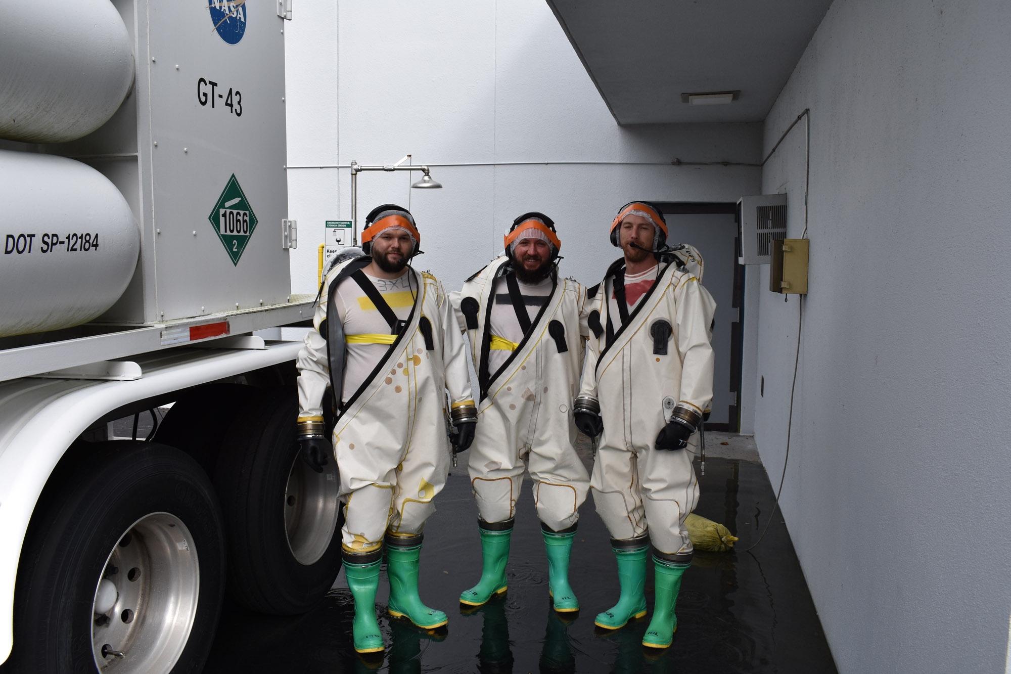
PACE Propellant Loading and Pressurization Procedure at Astrotech (Red Tag/Green Tag). Credit: NASA
Tracking and Delay Relay Satellites (TDRS) test photos. Launch Site integration and test: TDRS Live Sky at the Launch Site. Credit: NASA
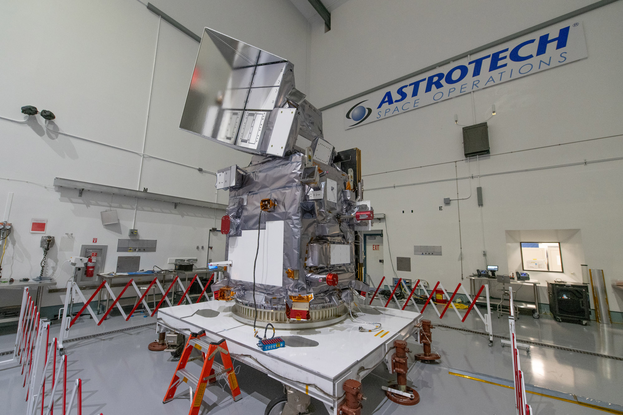
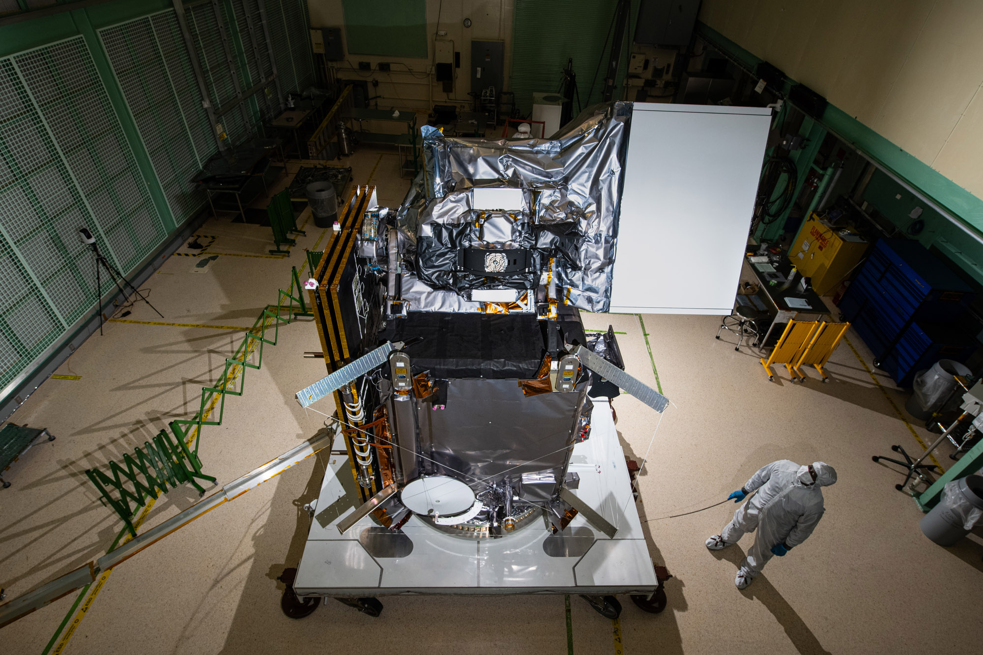
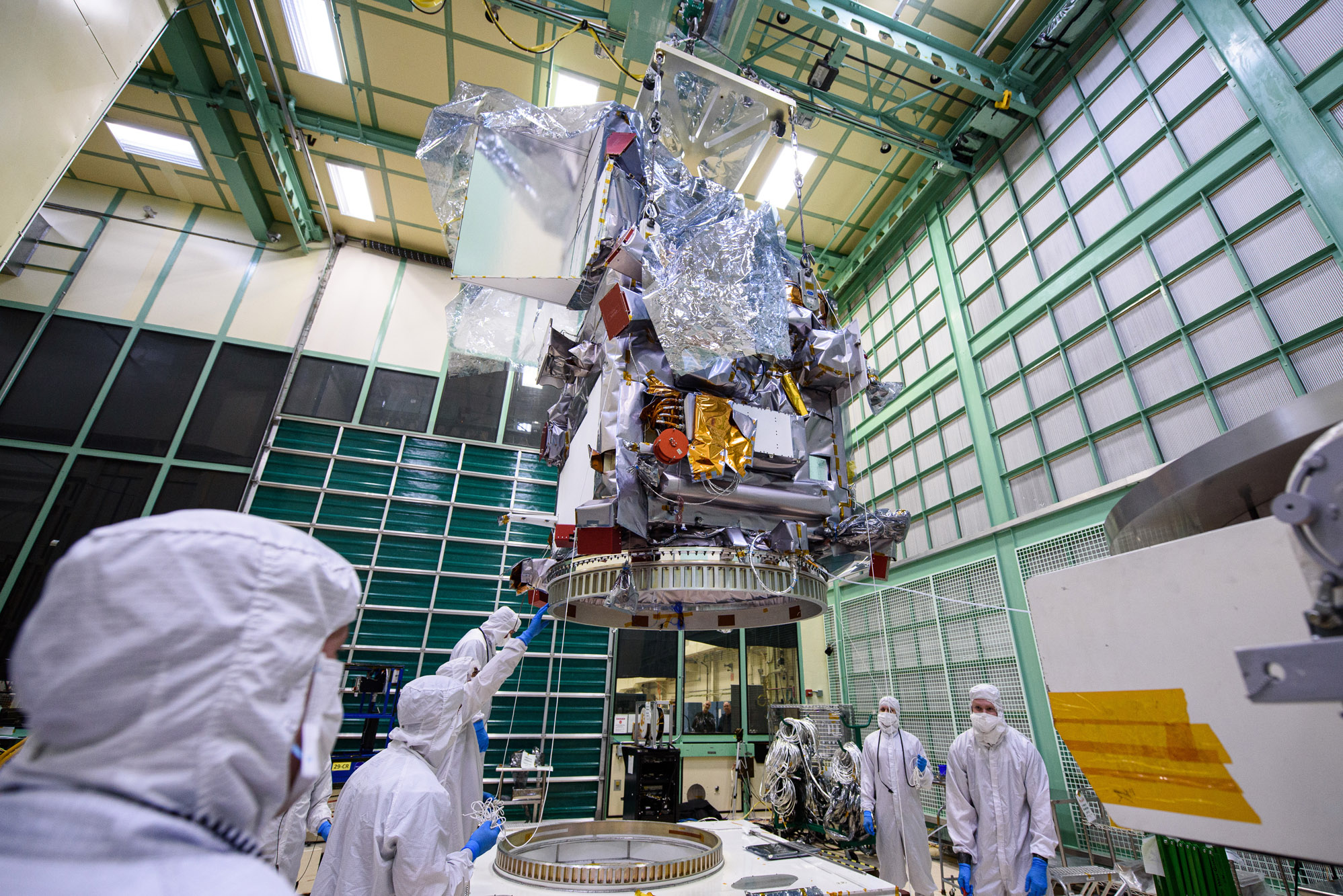
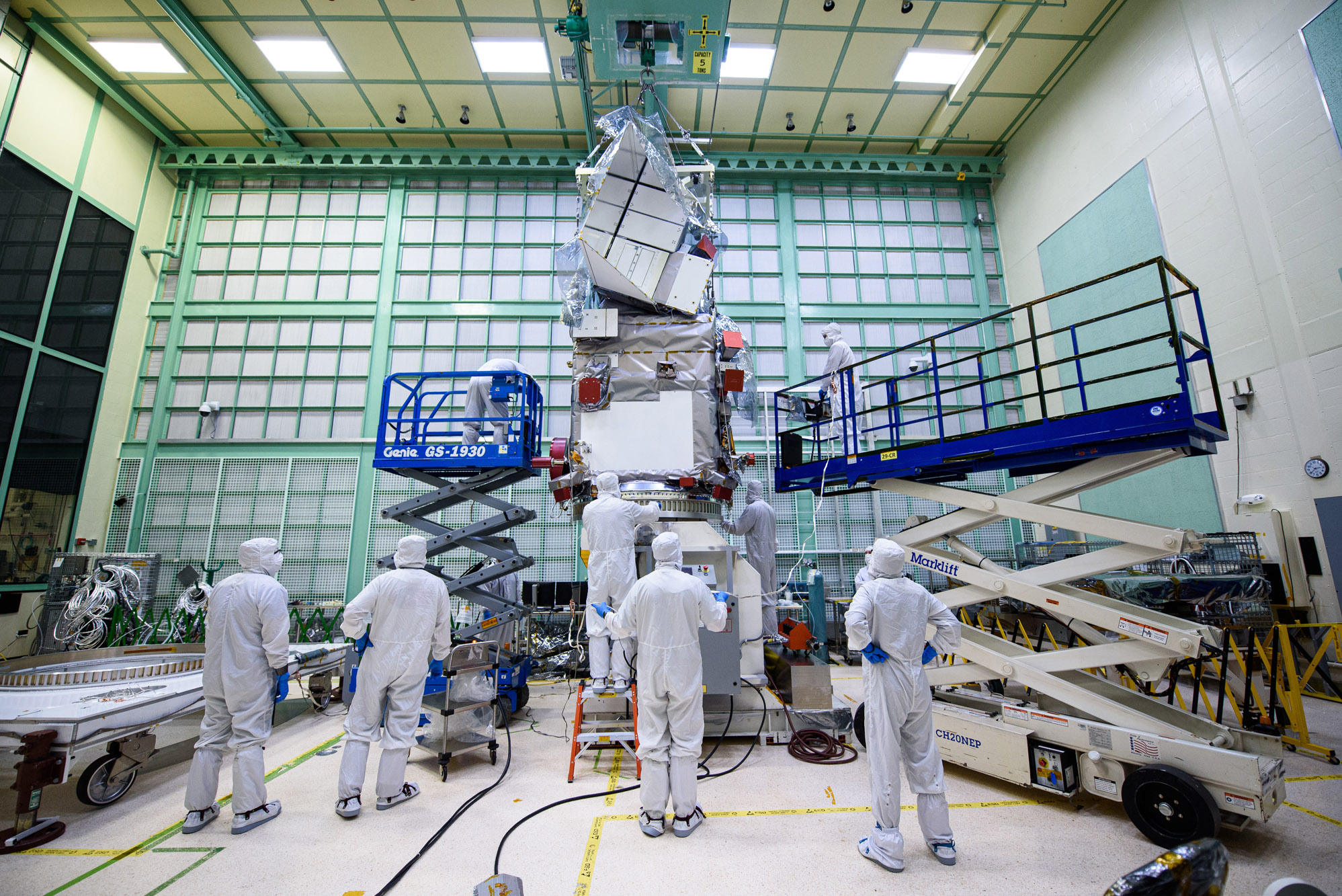
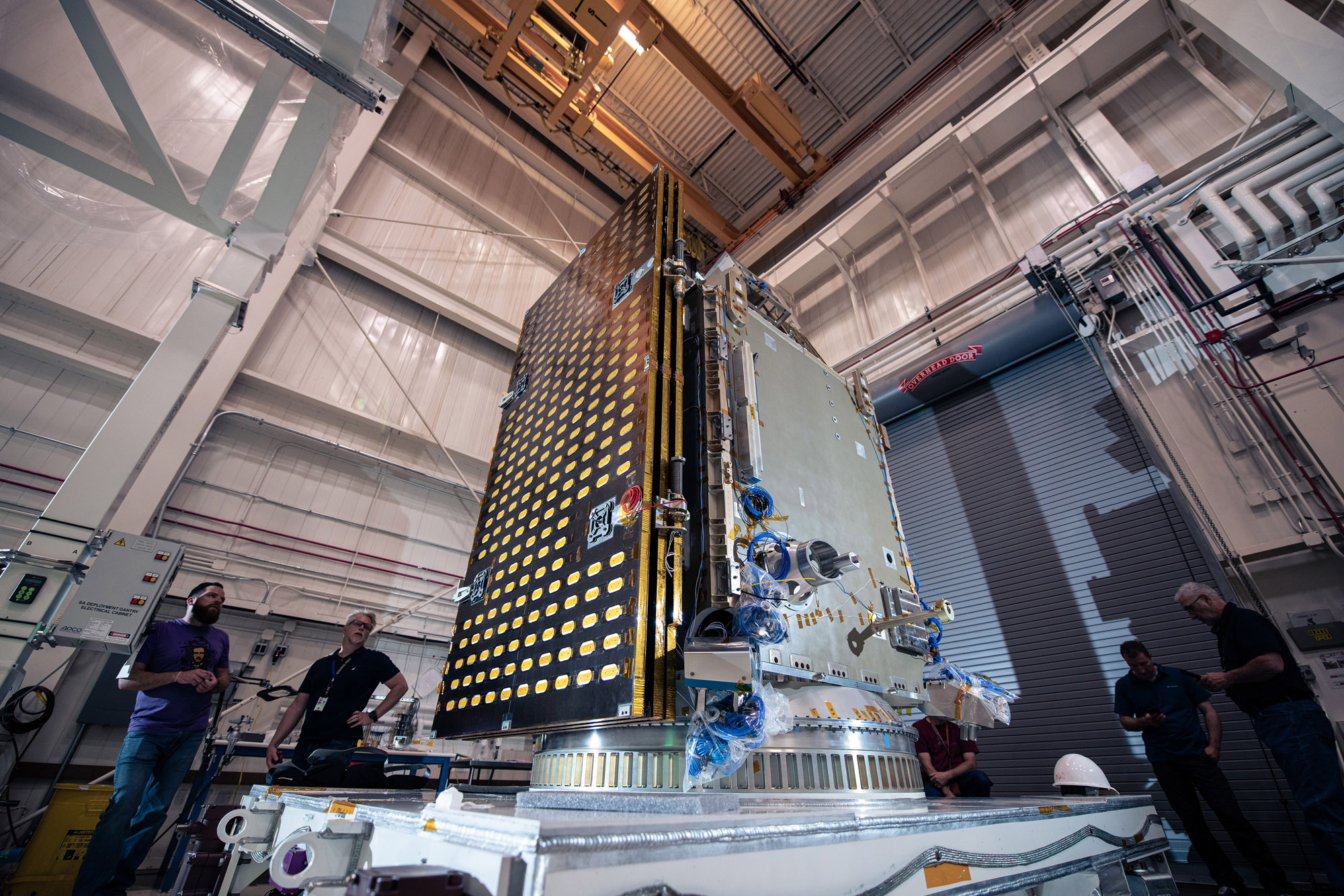
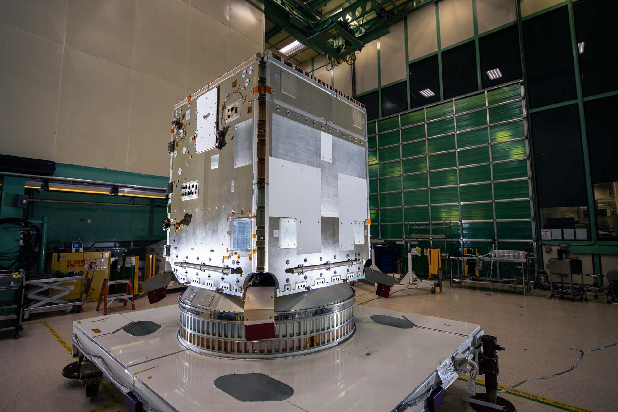
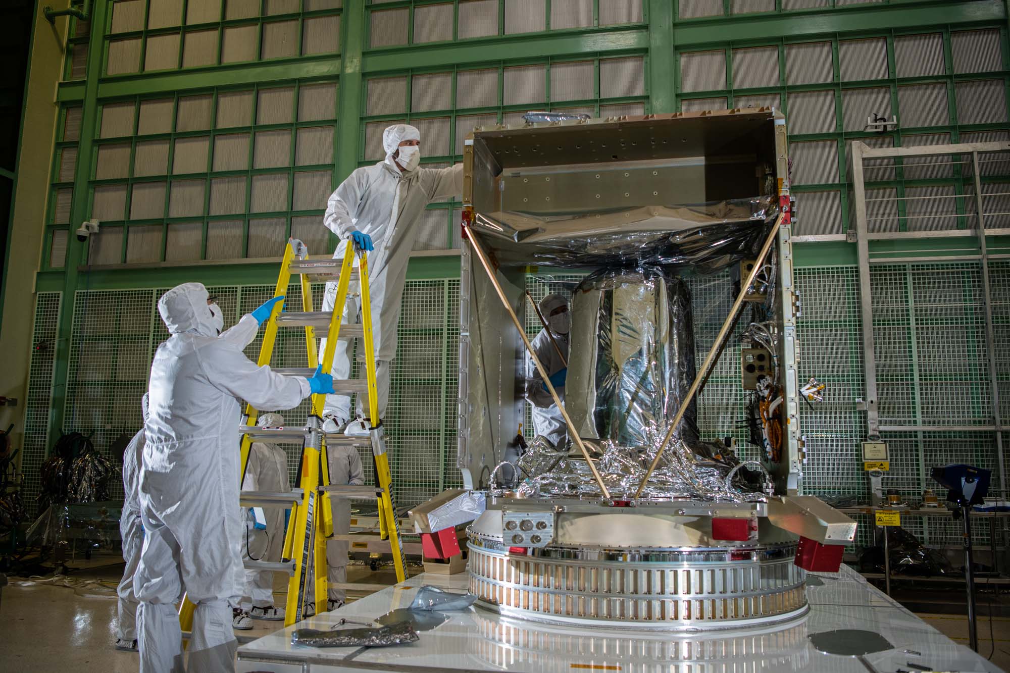
PACE Observatory on Dolly at Astrotech during Launch Campaign. Launch Site integration and test: Lift Observatory to Aronson Table. Lift Back to Observatory Dolly. Credit: NASA
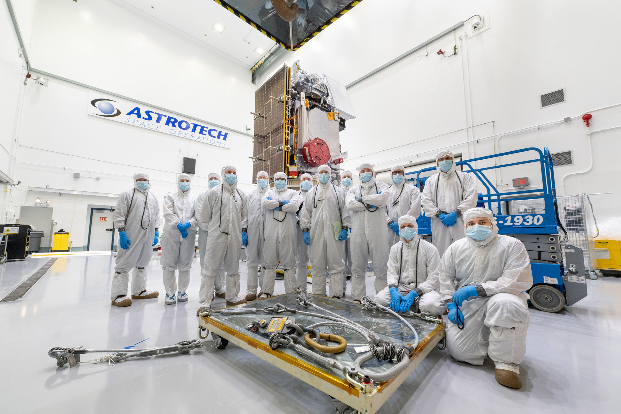
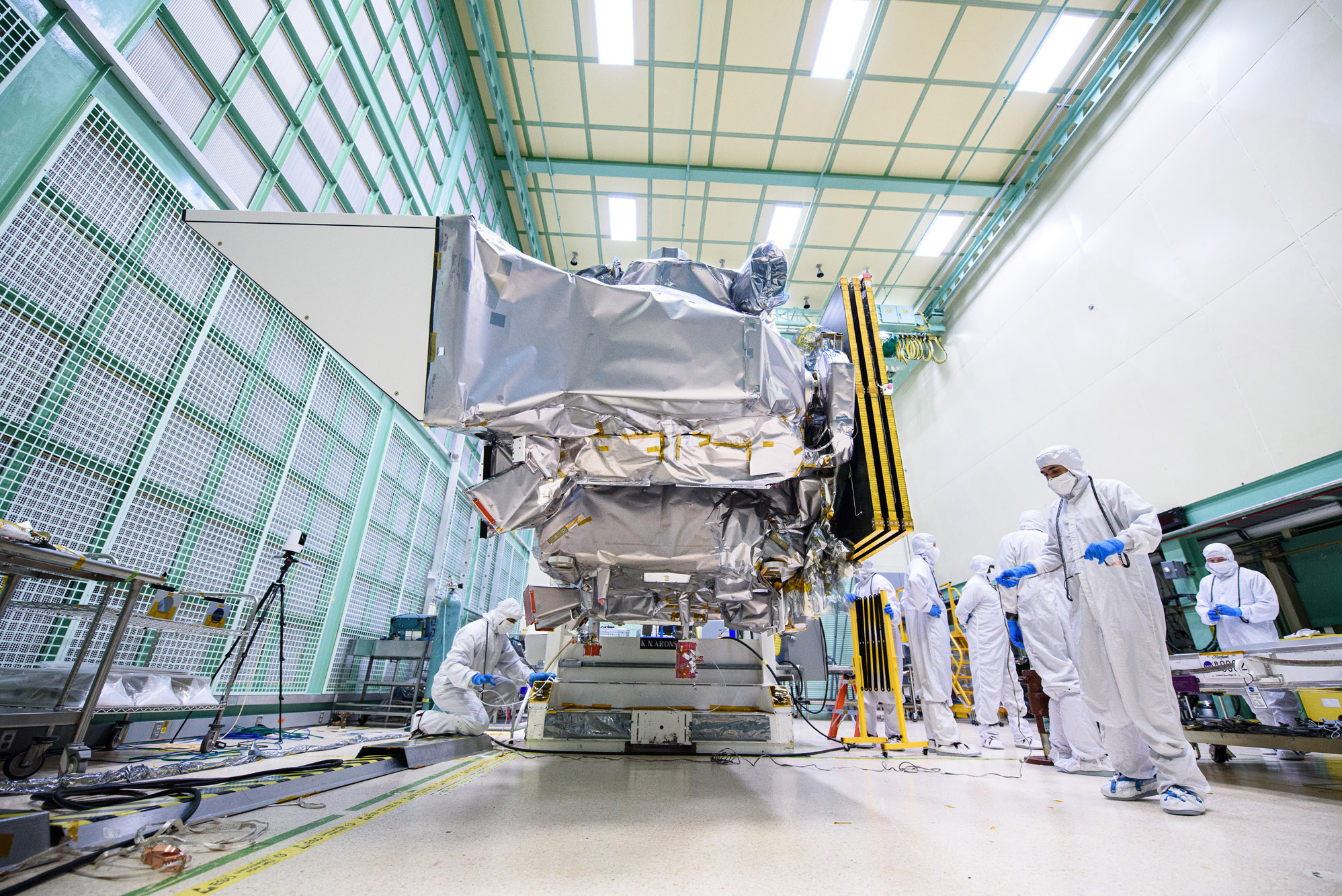
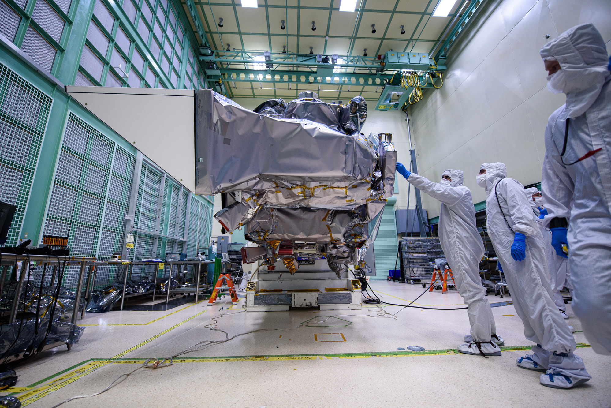
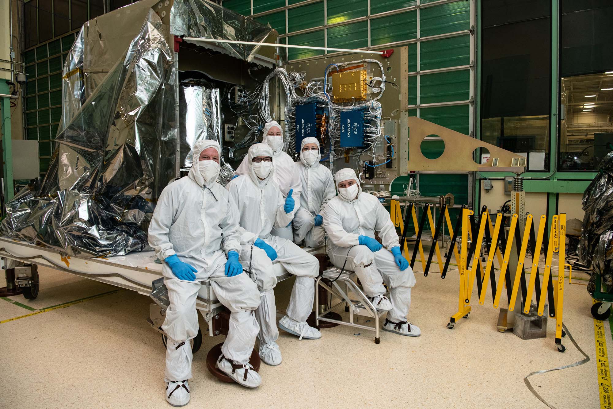
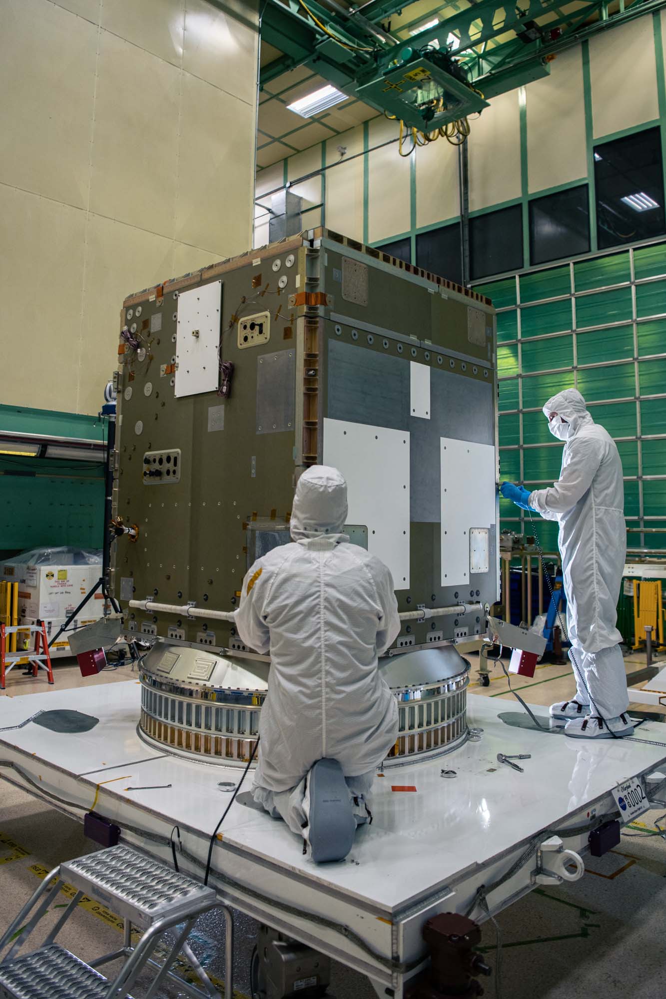
Mechanical Team Photo in front of PACE Observatory on Dolly at Astrotech during Launch Campaign. Credit: NASA
Launch Site integration and test. Lift Observatory to Aronson Table, Rotate for investigation, Lift Back to Observatory Dolly. Credit: NASA
Launch Site integration and test. Lift Observatory to Aronson Table, Rotate for investigation, Lift Back to Observatory Dolly. Credit: NASA
PACE observatory's arrival at Astrotech. Credit: NASA
PACE observatory's arrival at Astrotech. Credit: NASA
PACE Observatory transport to Astrotech. Credit: NASA
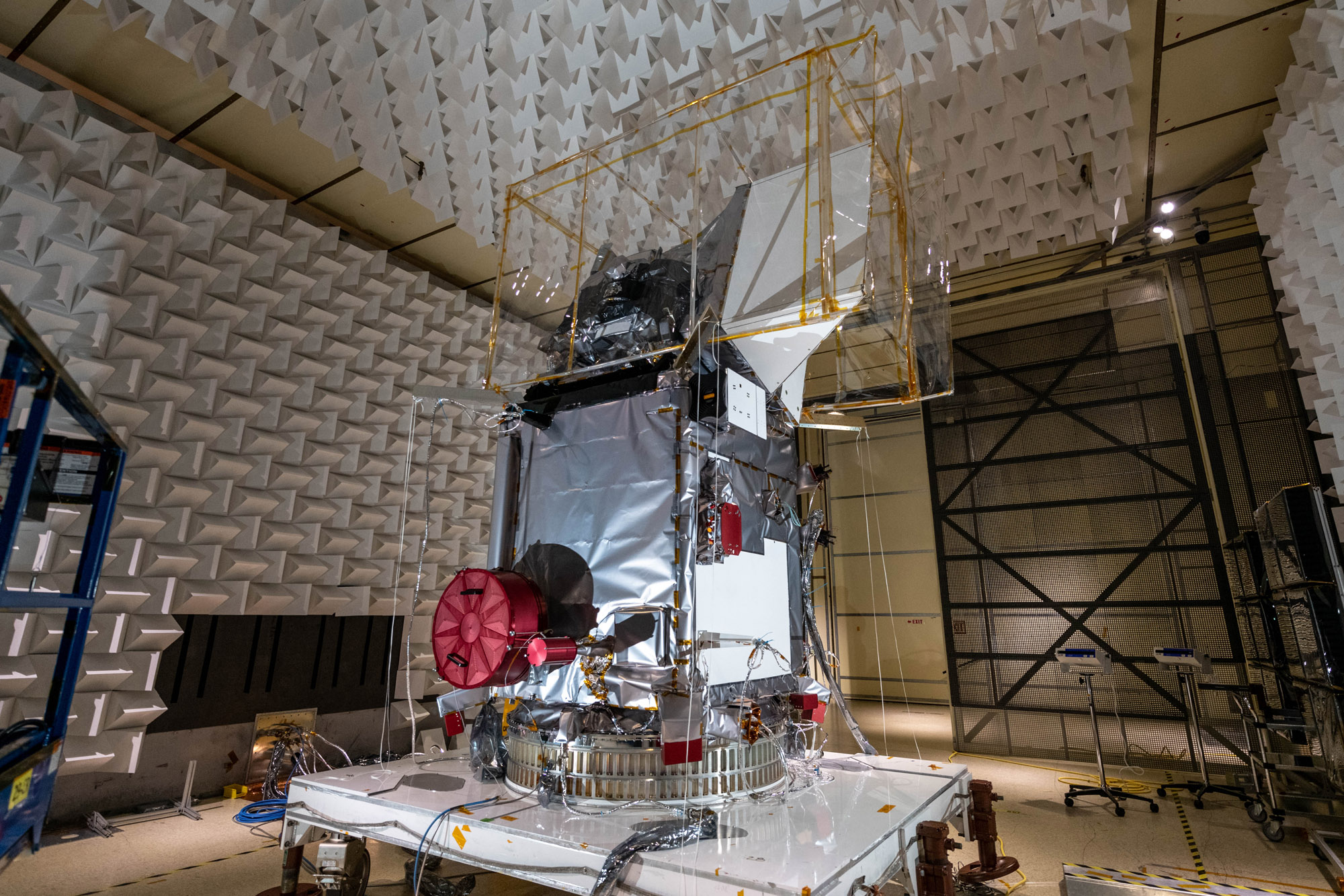
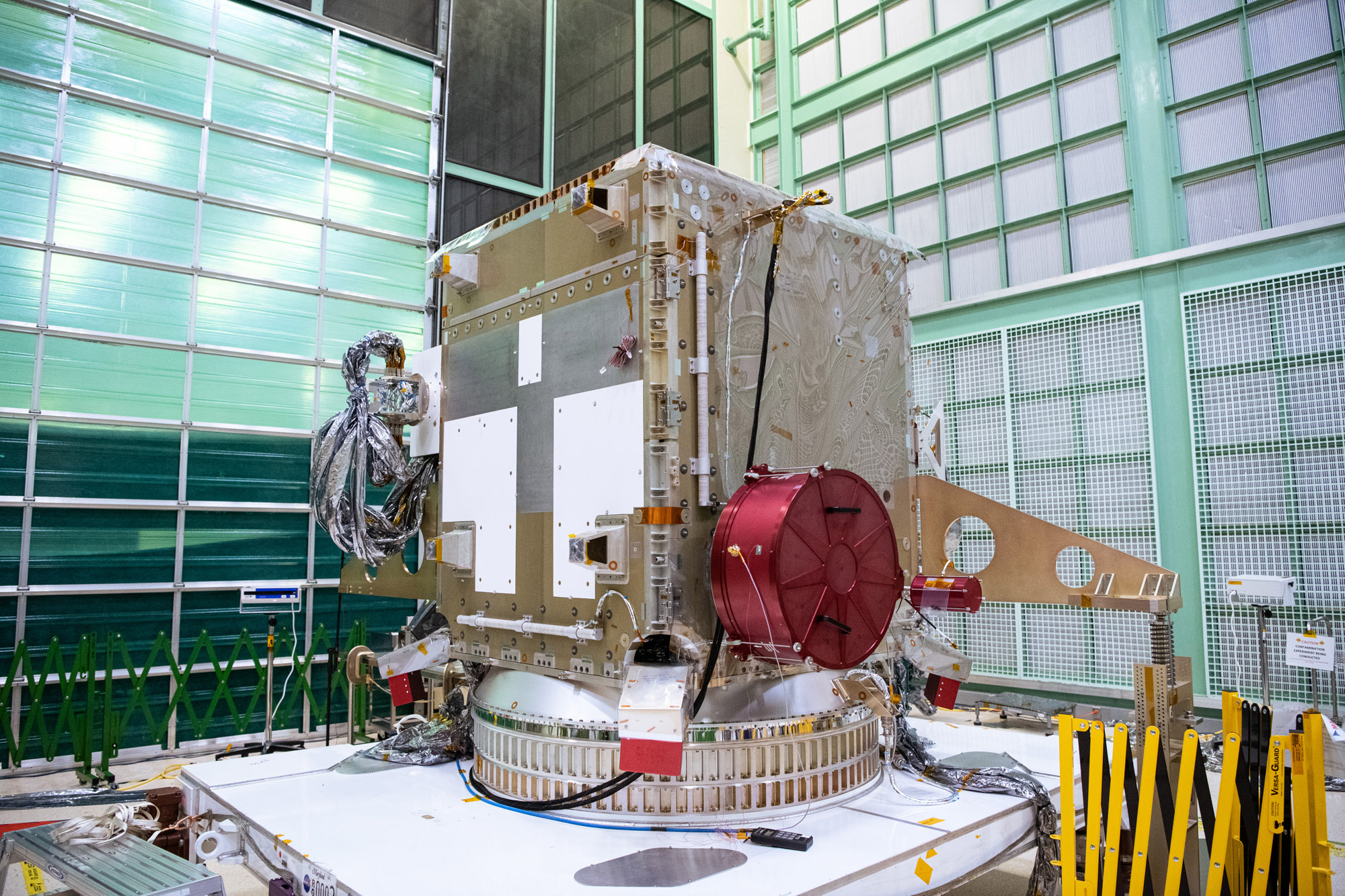
Glamour photo of PACE in the Spacecraft Checkout Area prior to shipment to Astrotech. Credit: NASA
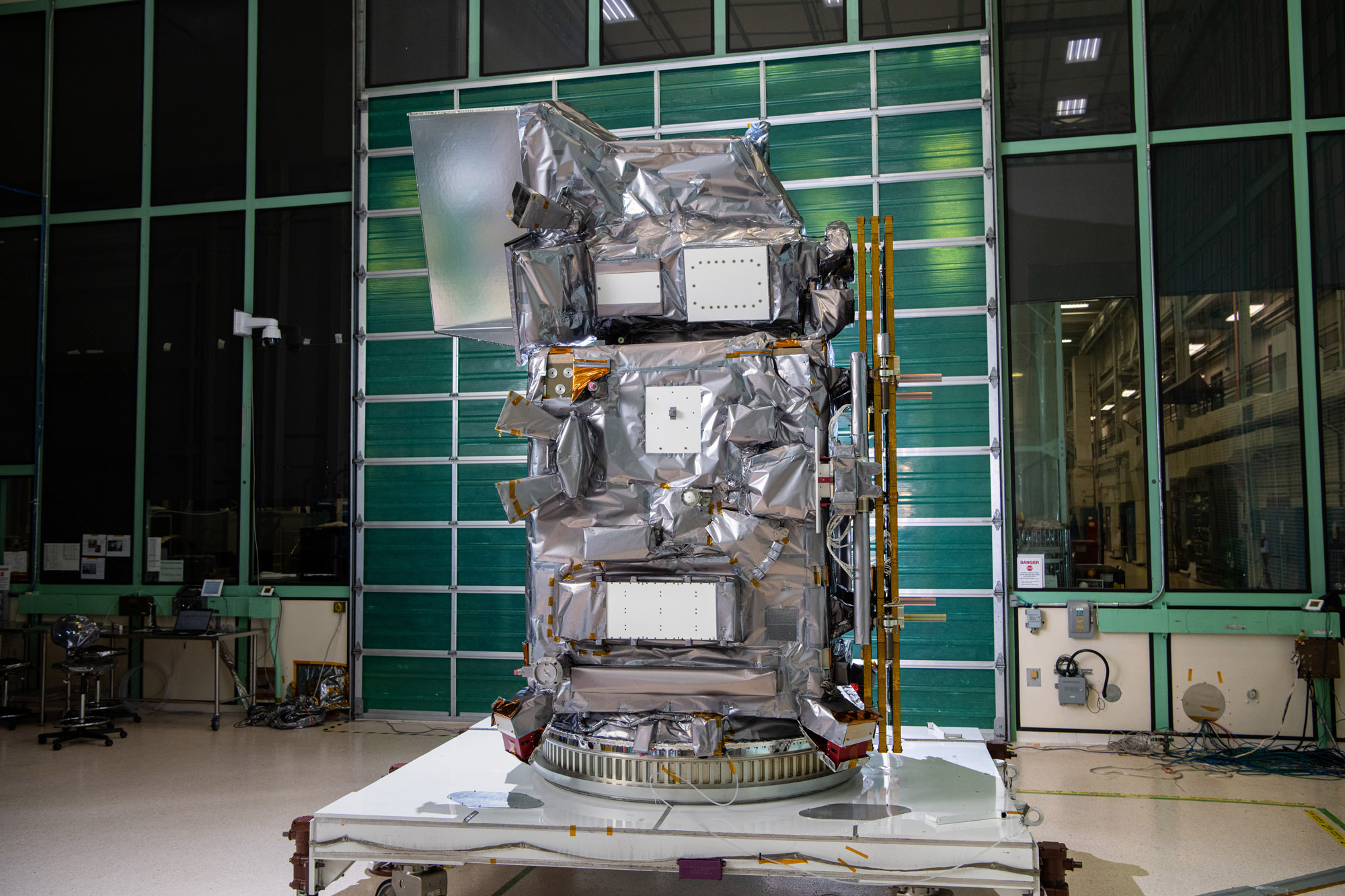
Glamour photo of PACE in the Spacecraft Checkout Area prior to shipment to Astrotech. Credit: NASA
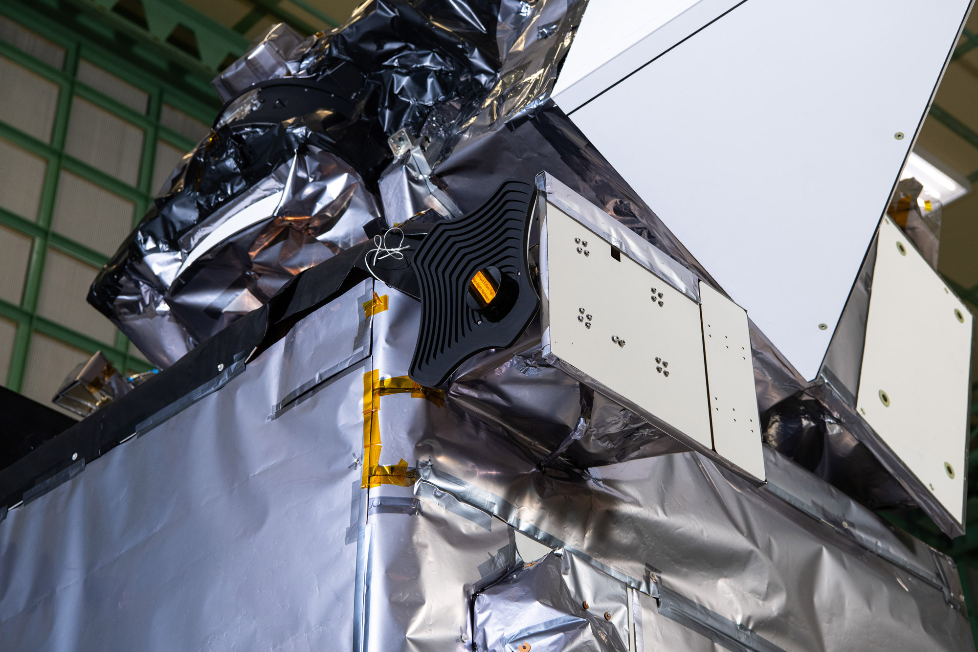
Glamour photo of PACE in the Spacecraft Checkout Area prior to shipment to Astrotech. Credit: NASA
Glamour photo of PACE in the Spacecraft Checkout Area prior to shipment to Astrotech. Credit: NASA
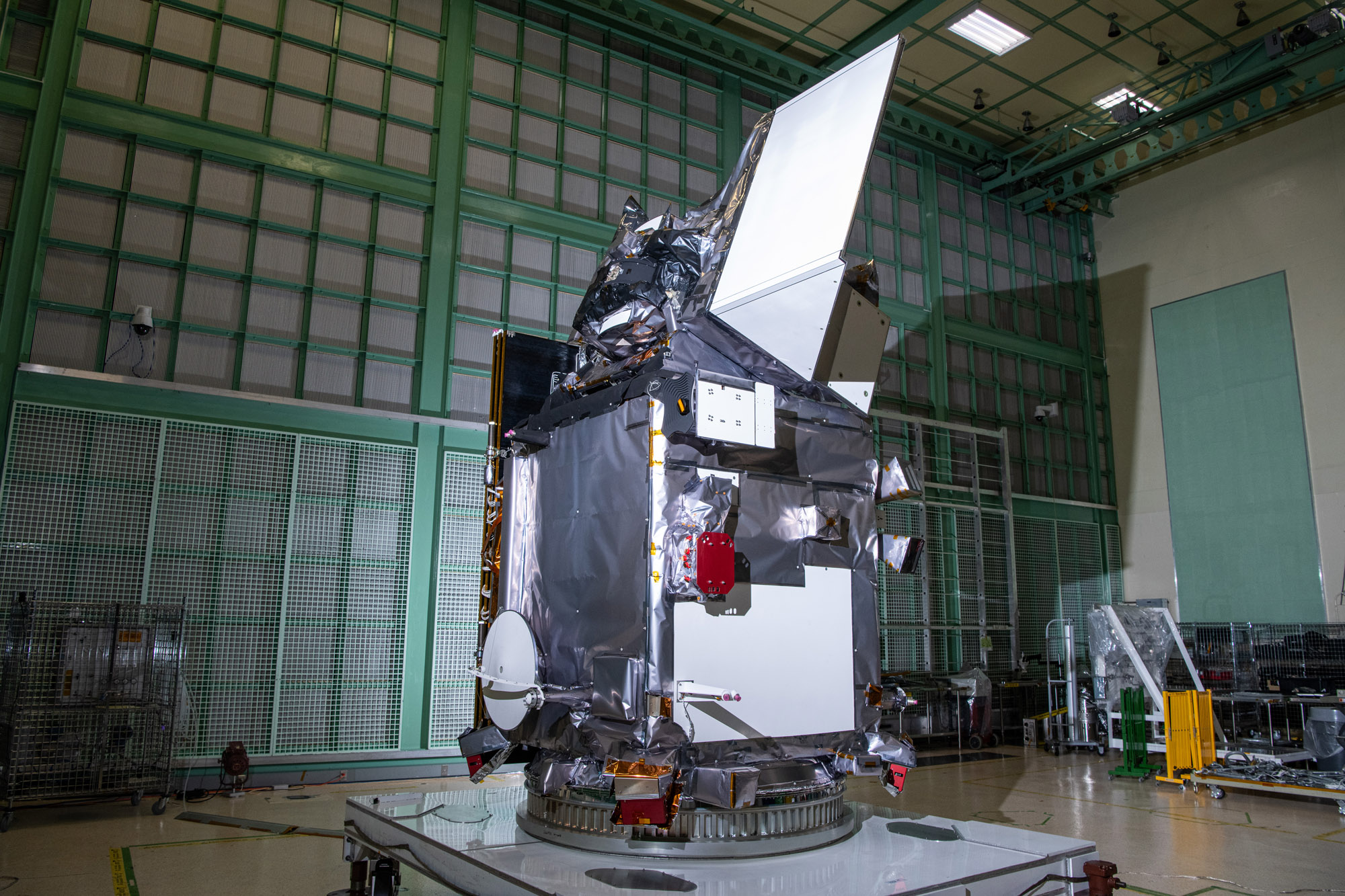
Glamour photo of PACE in the Spacecraft Checkout Area prior to shipment to Astrotech. Credit: NASA
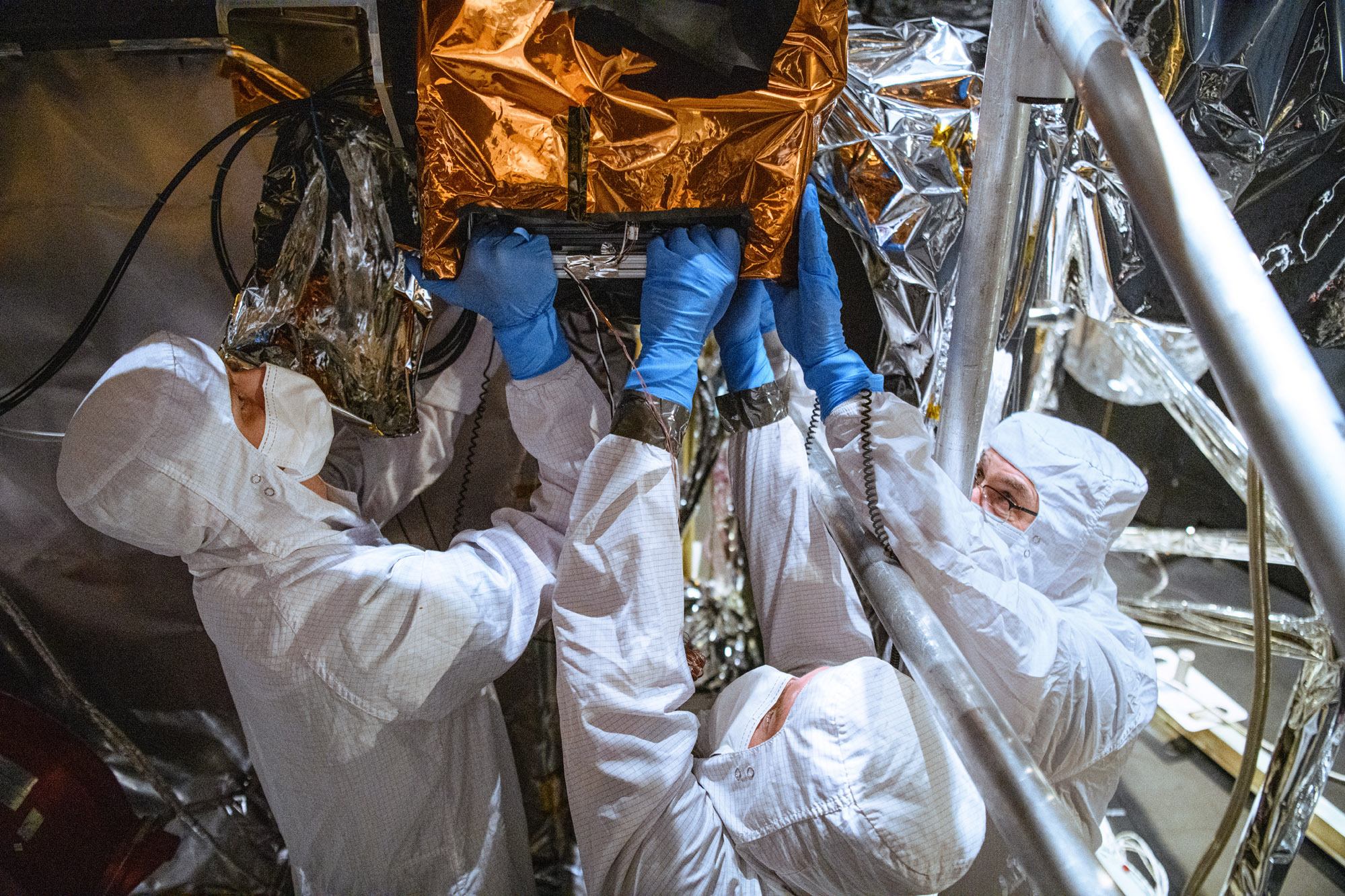
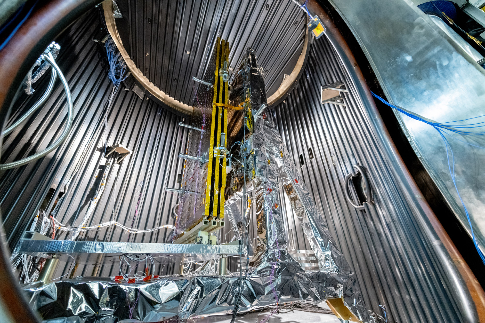
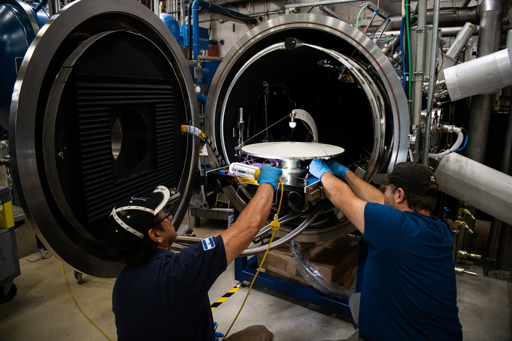
PACE Observatory thermal vacuum testing: Configure for Thermal Vacuum Test (Chamber Break); HARP2 sphere lift. Credit: NASA
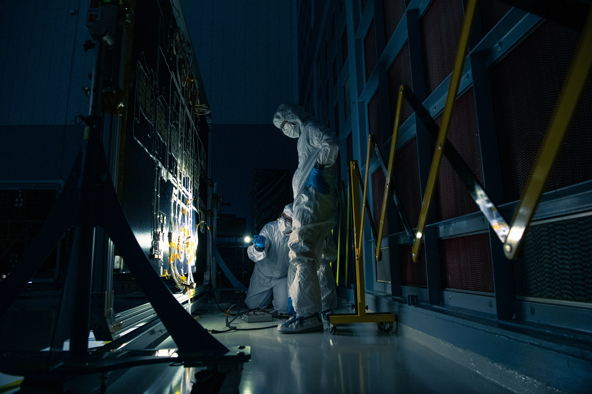
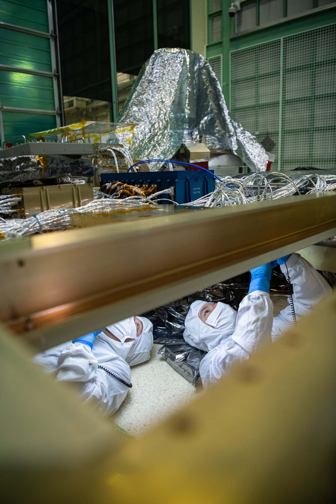
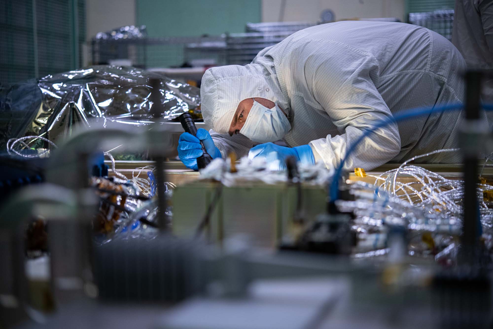
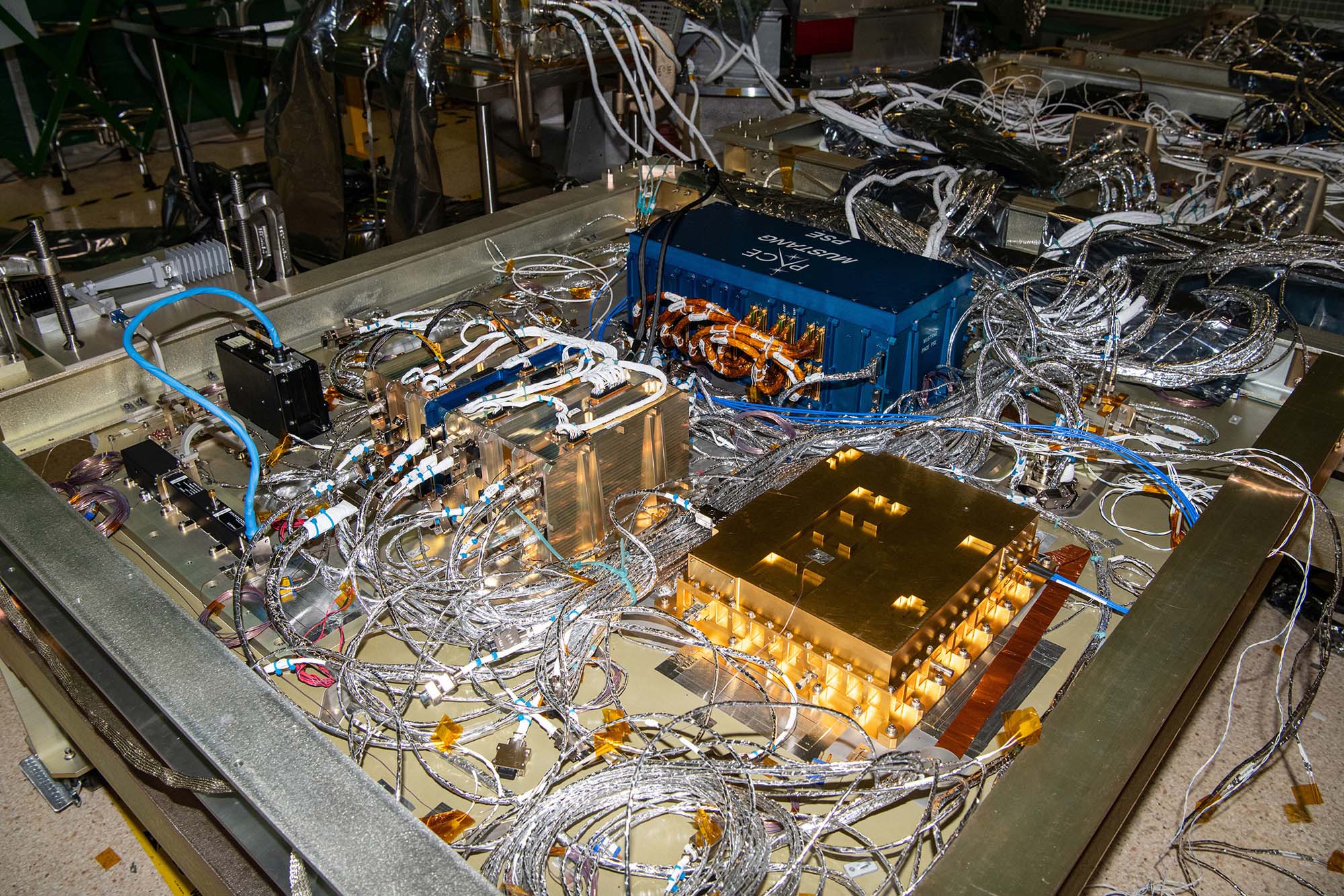
Observatory integration and test: Walkdown Observatory Space Environment Simulator Chamber and Ground Support Equipment Racks Prior to Chamber Closing. Quick overall photo of observatory and setup during prep and walkdown. Credit: NASA
Observatory integration and test: Walkdown Observatory Space Environment Simulator Chamber and Ground Support Equipment Racks Prior to Chamber Closing. Credit: NASA
Observatory integration and test: Walkdown Observatory Space Environment Simulator Chamber and Ground Support Equipment Racks Prior to Chamber Closing. Credit: NASA
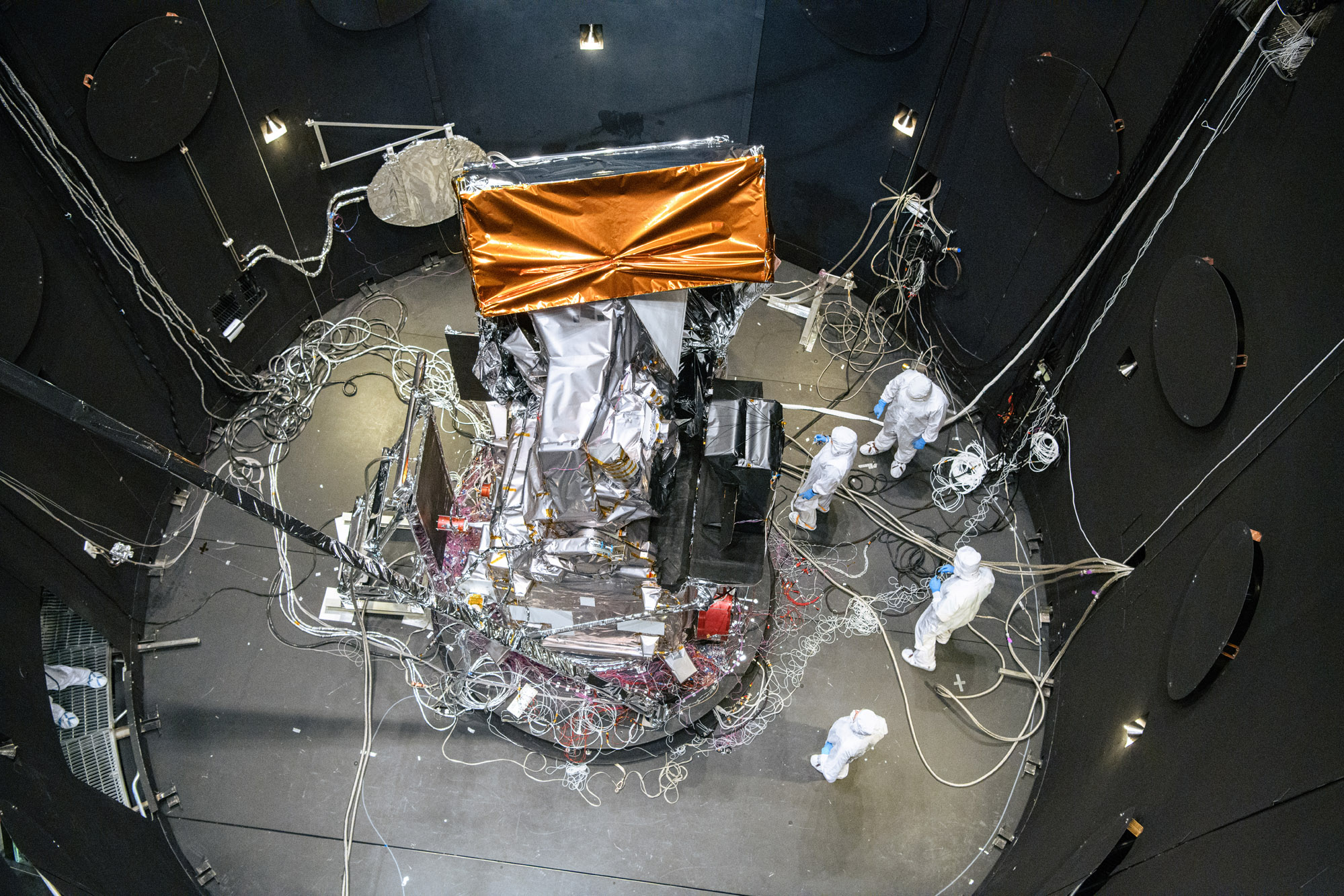
Observatory integration and test: Walkdown Observatory Space Environment Simulator Chamber and Ground Support Equipment Racks Prior to Chamber Closing. Credit: NASA
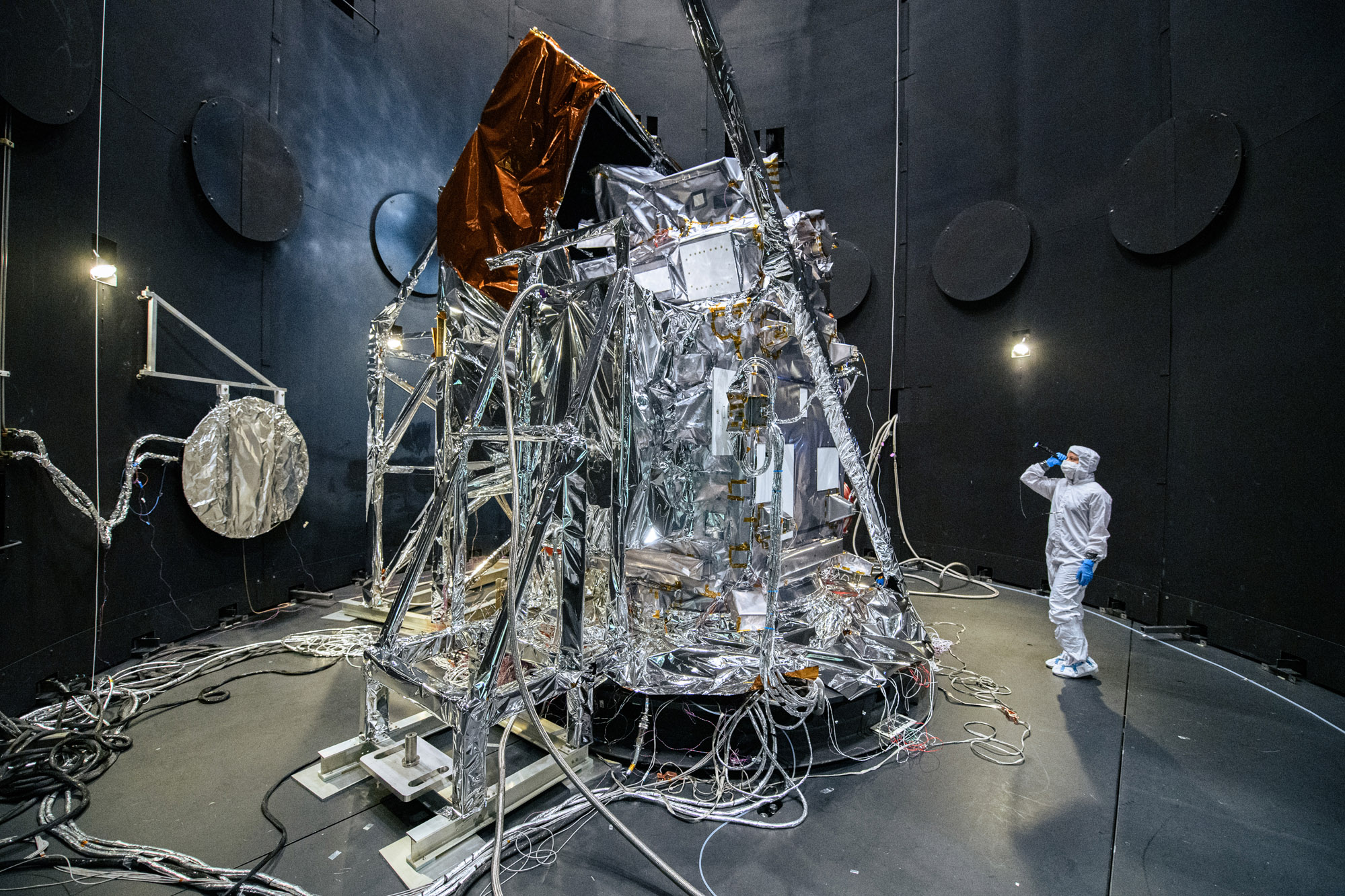
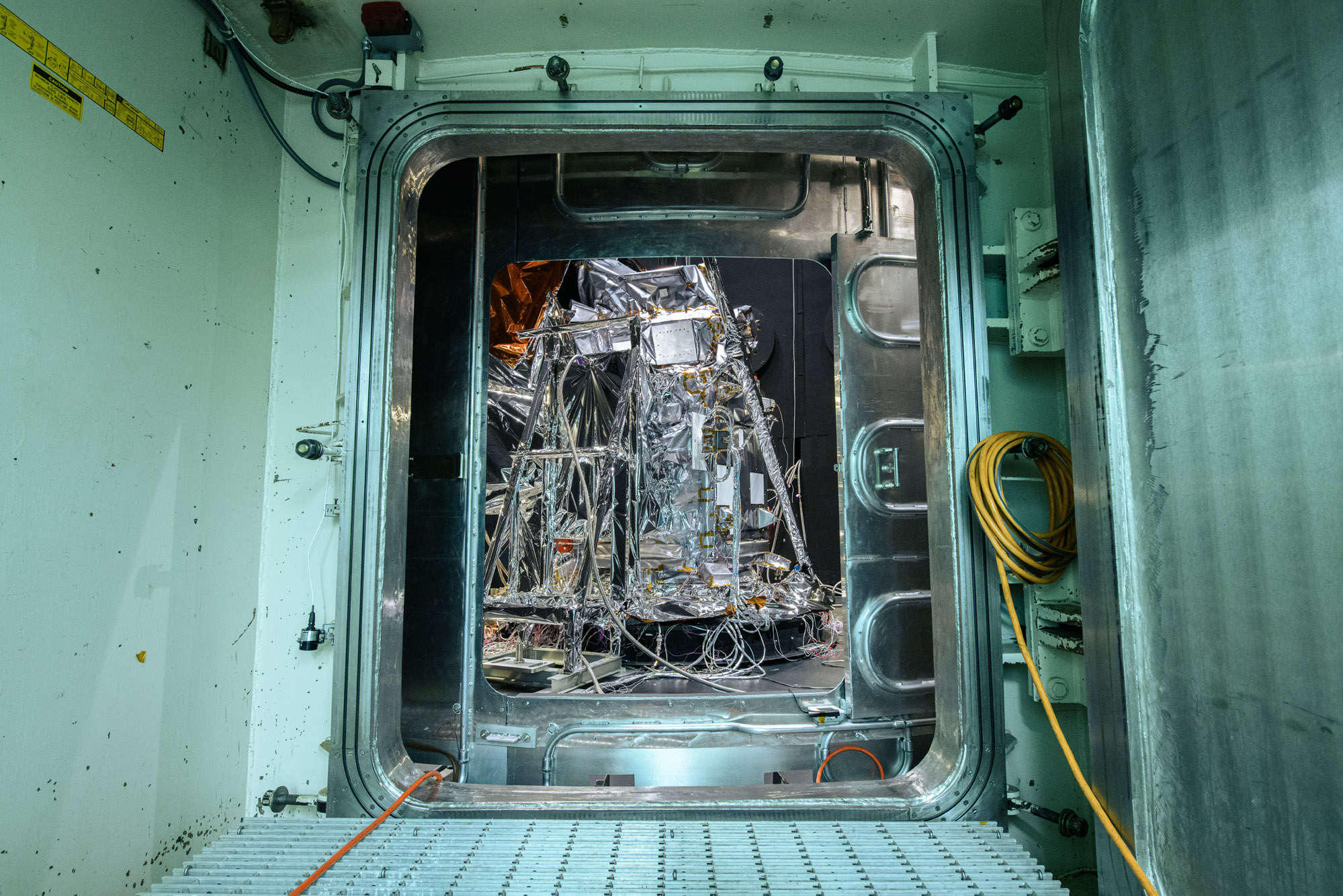
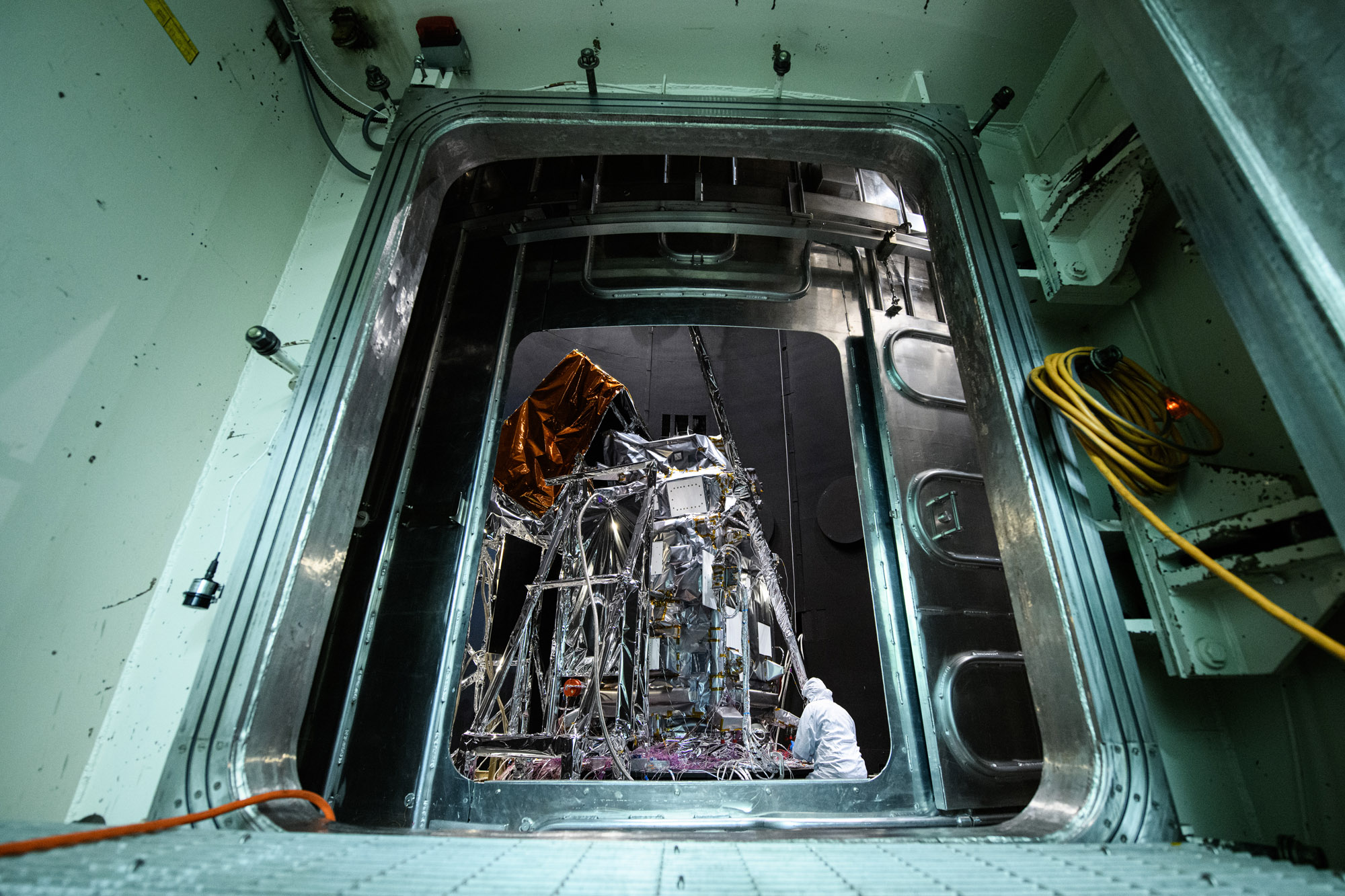
Stage the Observatory outside the Space Environment Simulator Chamber 290; Move Observatory to the Chamber for testing. Credit: NASA
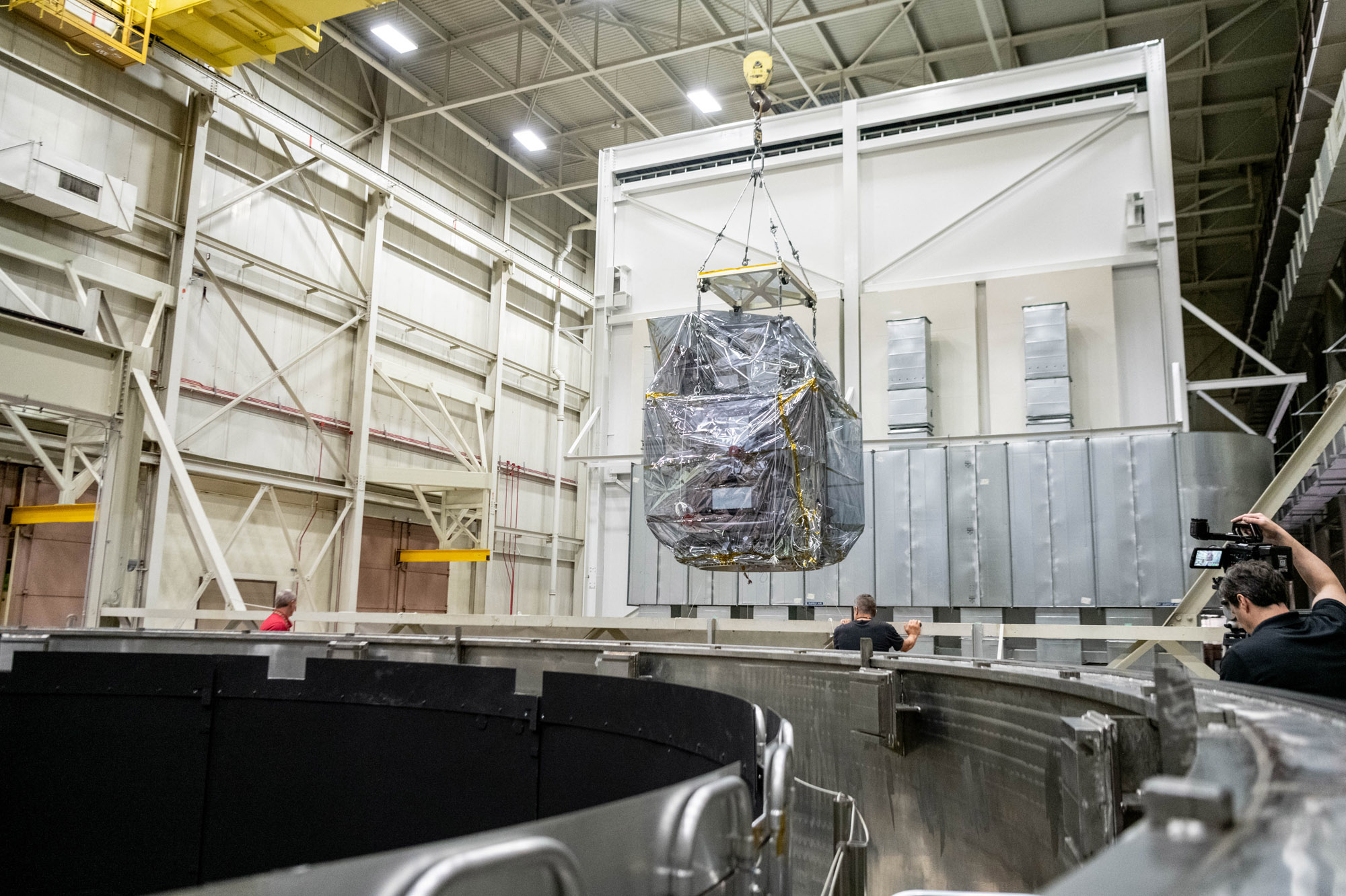
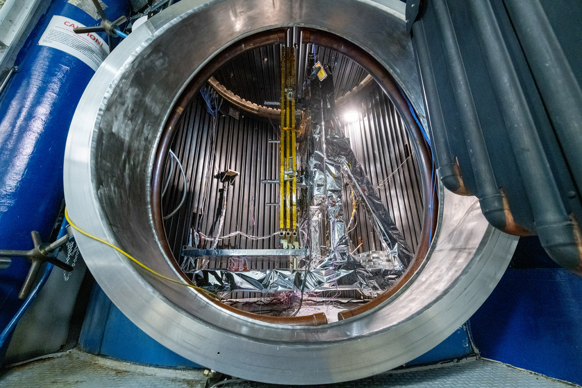
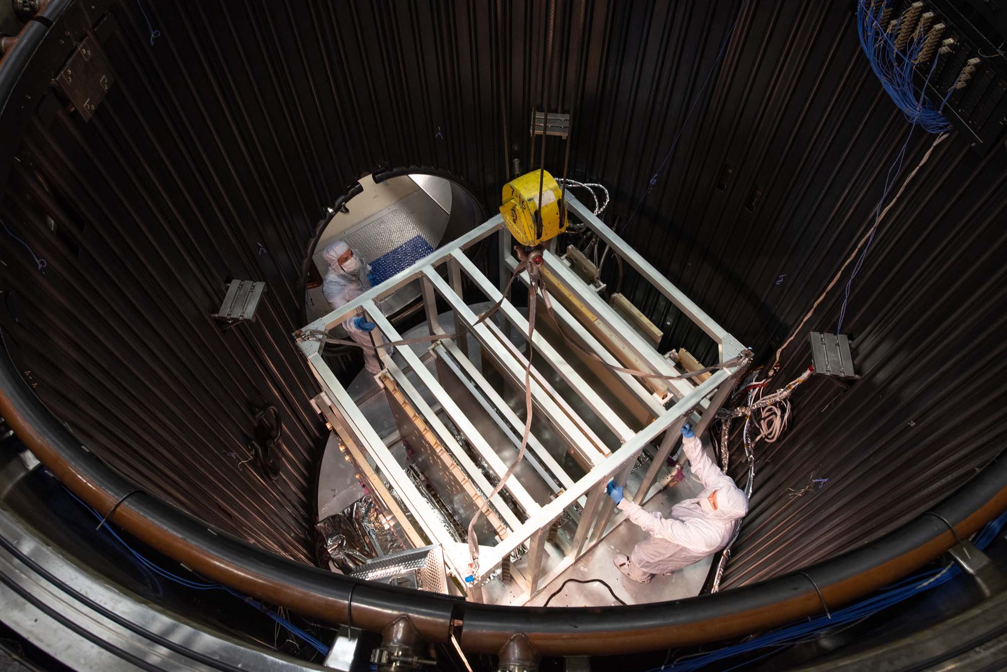
Lift the Observatory into the Space Environment Simulator (SES) Chamber; PACE Observatory thermal vacuum Testing: Lift into SES and Configure for testing. Credit: NASA
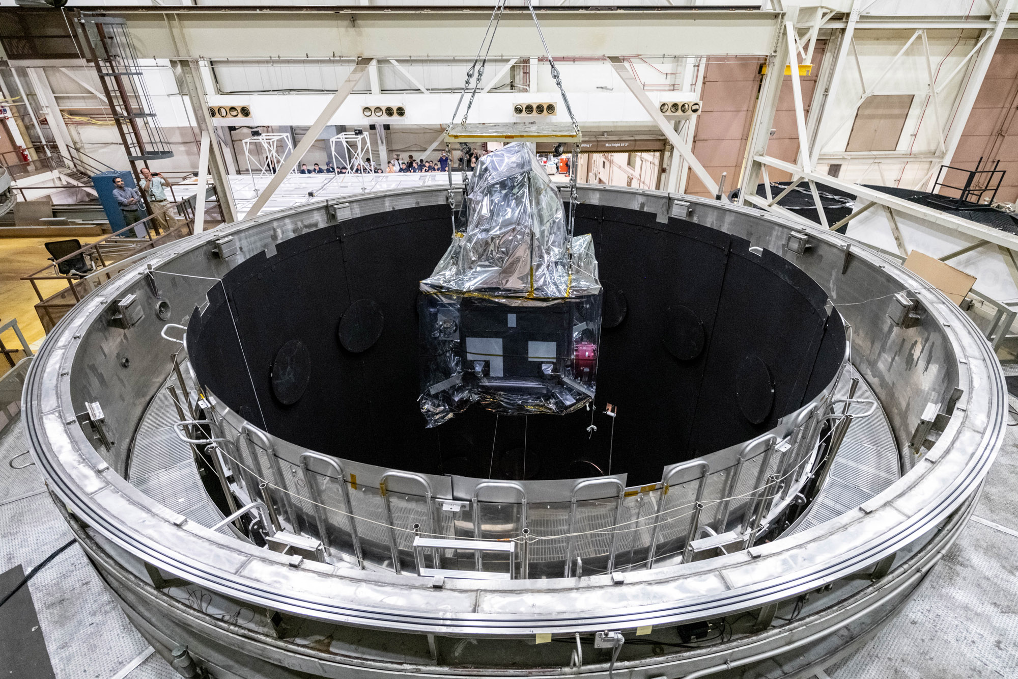
Lift the Observatory into the Space Environment Simulator (SES) Chamber; PACE Observatory thermal vacuum Testing: Lift into SES and Configure for testing. Credit: NASA
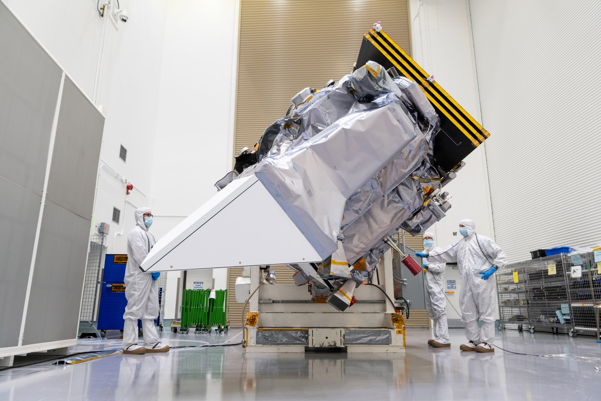
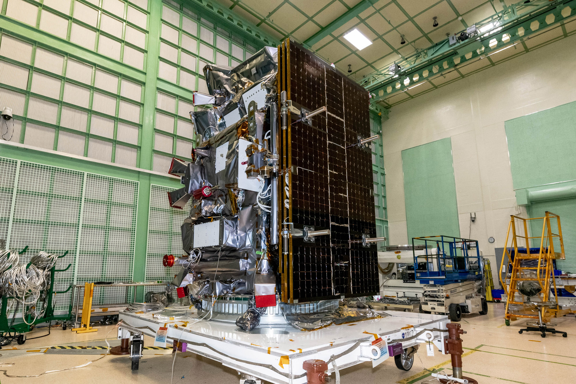
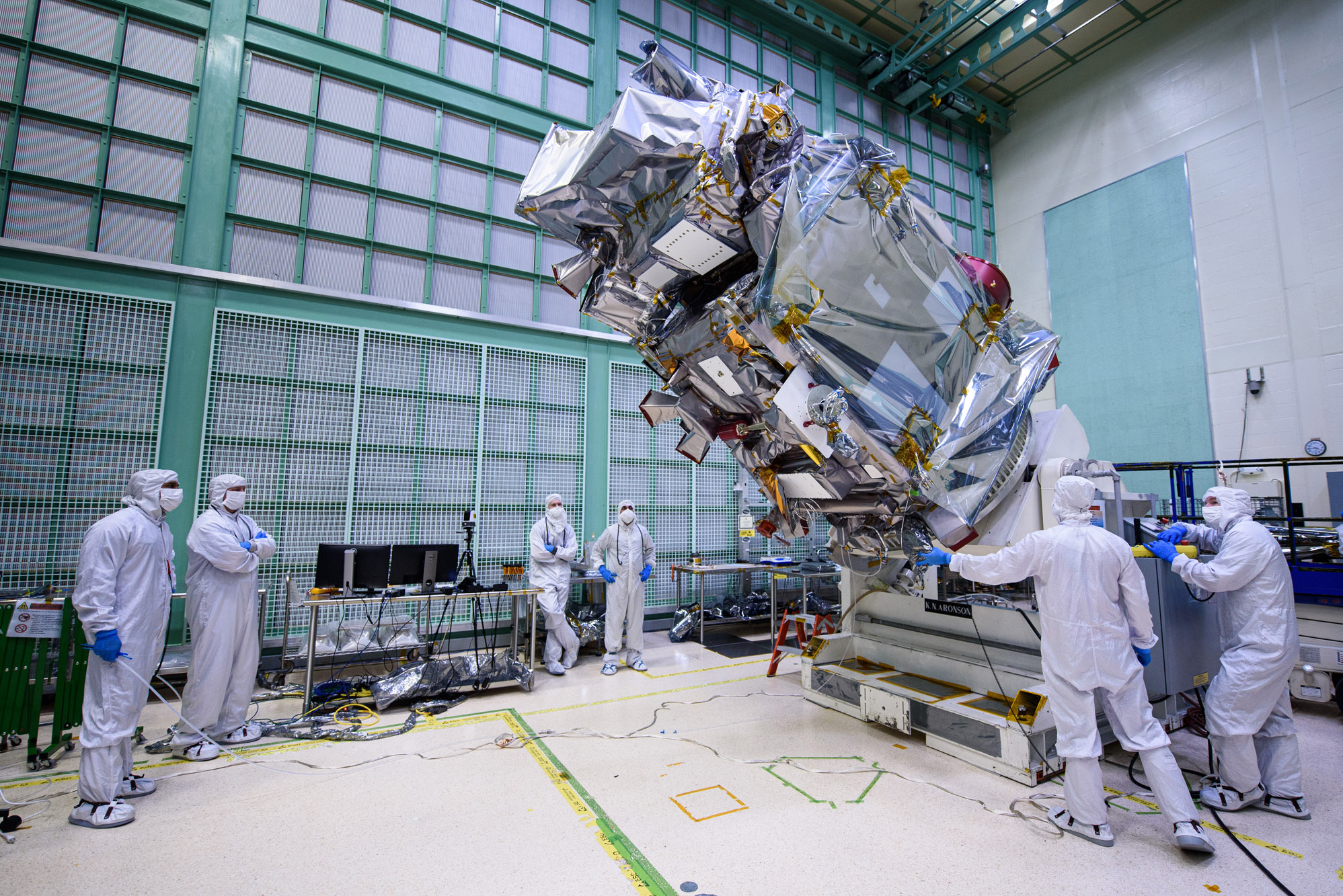
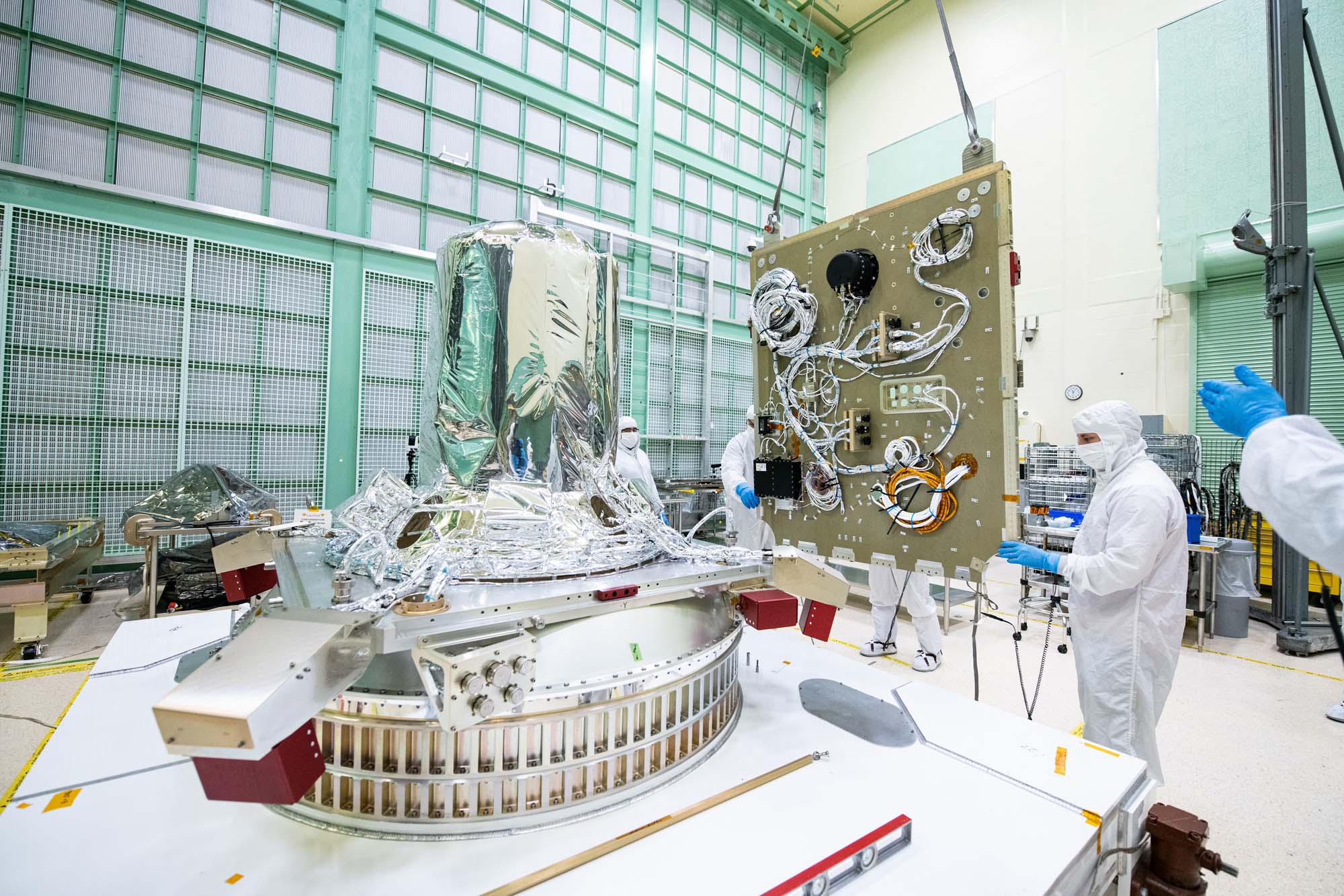
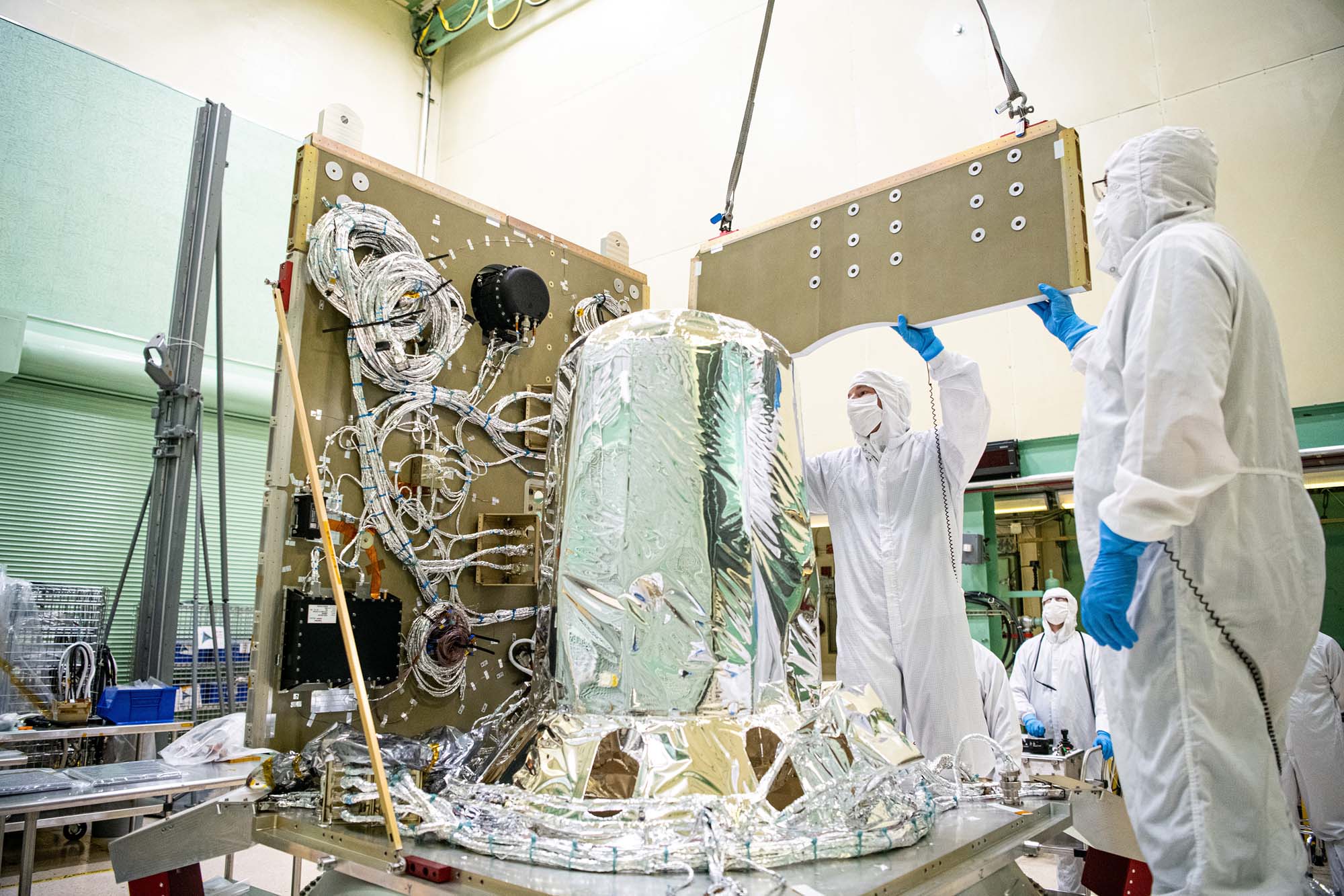
Lift Observatory to Aronson Table. Rotate for Flight Solar Array Wing Removal and Lift Back to Observatory Dolly; Tilt down Aronson table with +Z panel up. Credit: NASA
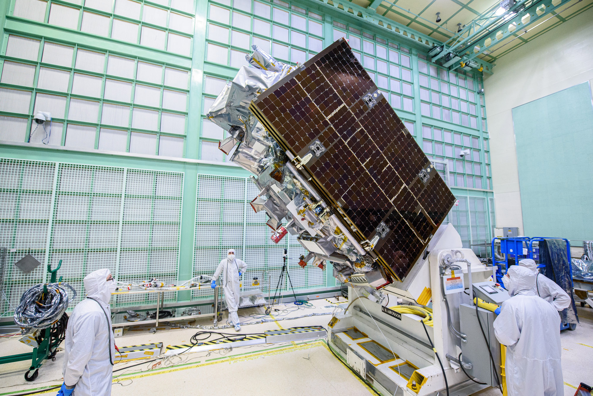
Lift Observatory to Aronson Table, Rotate for Flight Solar Array Wing Removal and Lift Back to Observatory Dolly; Tilt down Aronson table with +Z panel up. Credit: NASA
Lift Observatory to Aronson Table, Rotate for Flight Solar Array Wing Removal and Lift Back to Observatory Dolly; Lift of the observatory off the dolly to the Aronson table. Credit: NASA
Lift Observatory to Aronson Table. Rotate for Flight Solar Array Wing Removal and Lift Back to Observatory Dolly; Lift of the observatory off the dolly to the Aronson table. Credit: NASA
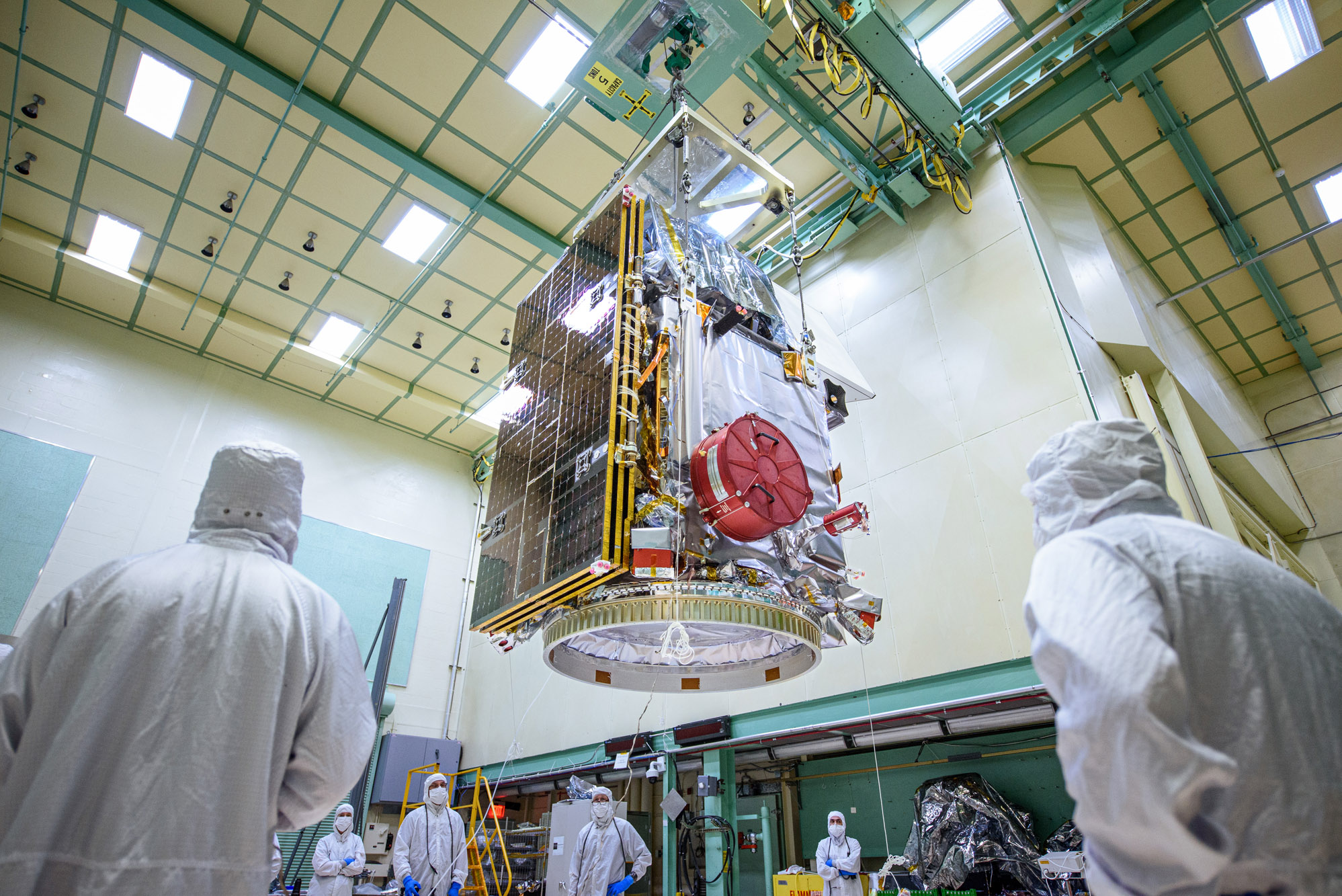
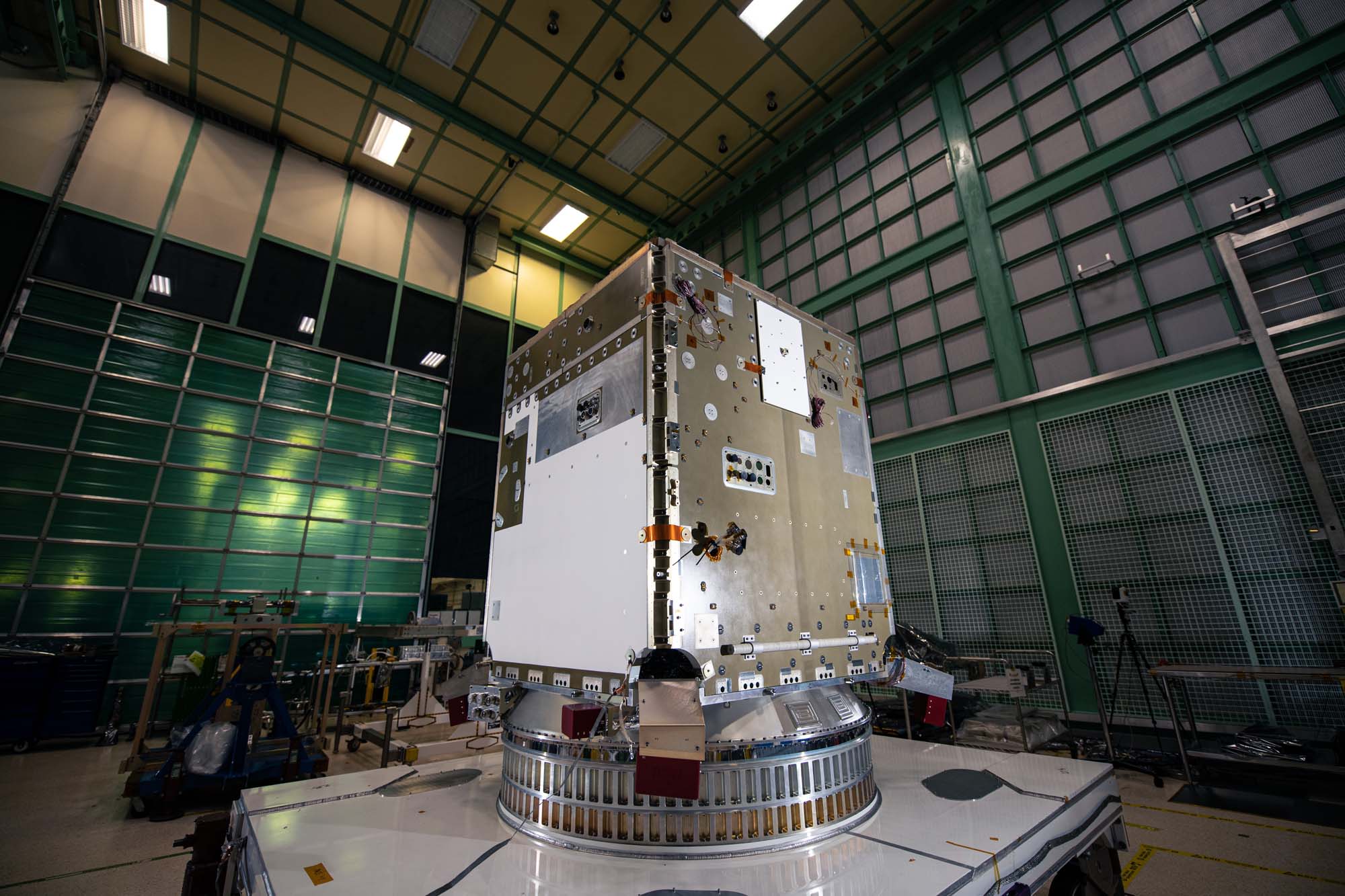
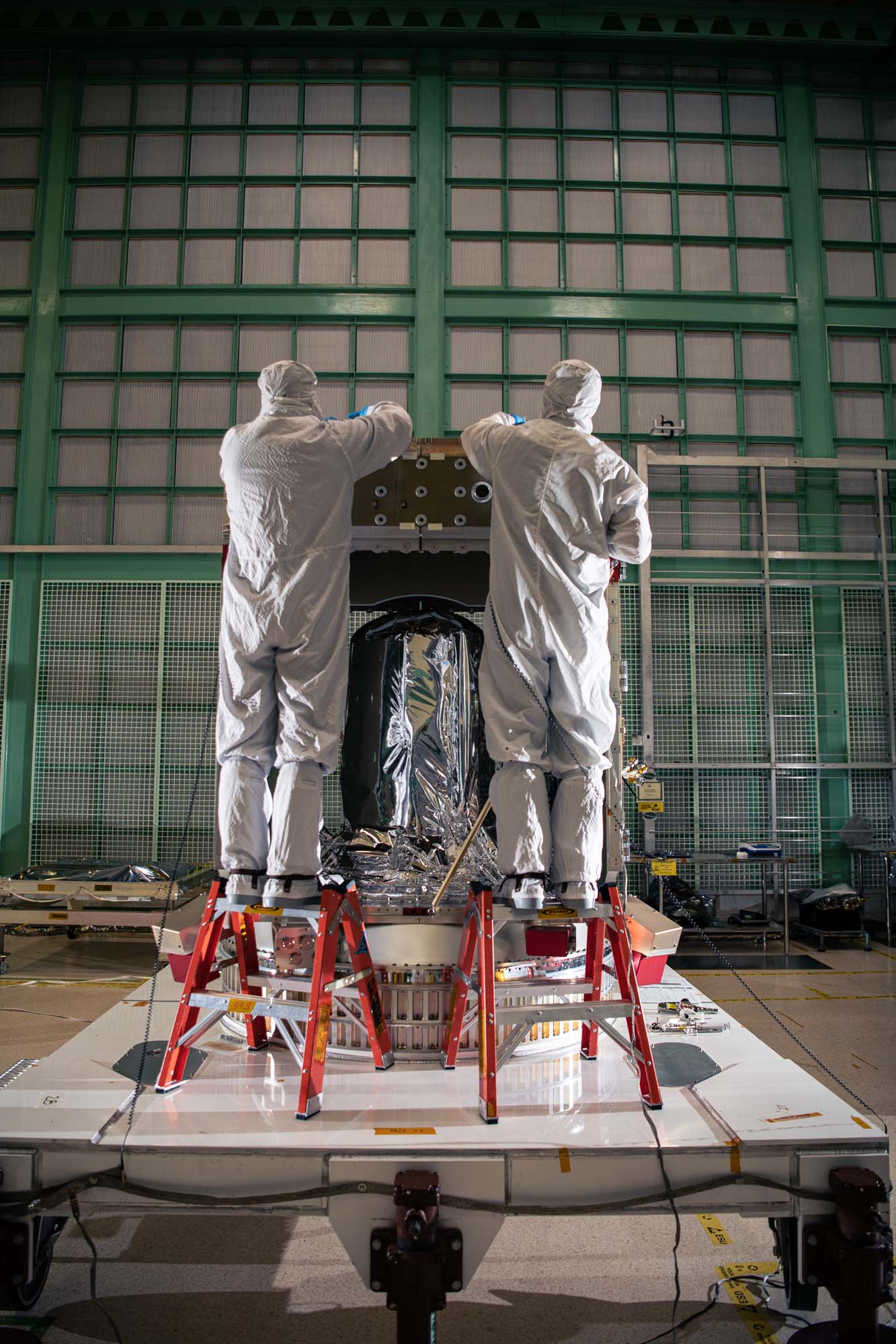
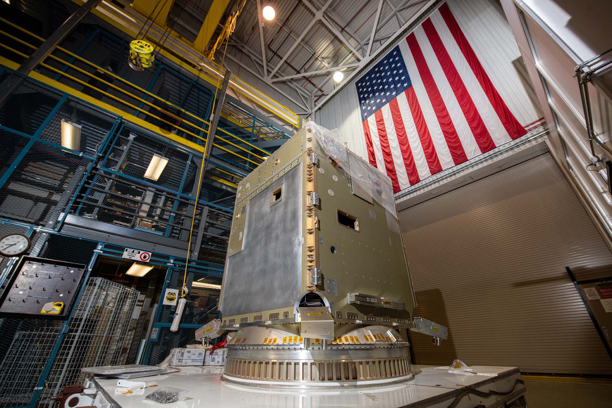
Final spacecraft configuration in Spacecraft Checkout Area (SCA). Prep, bag and move the Observatory to SCA. Credit: NASA
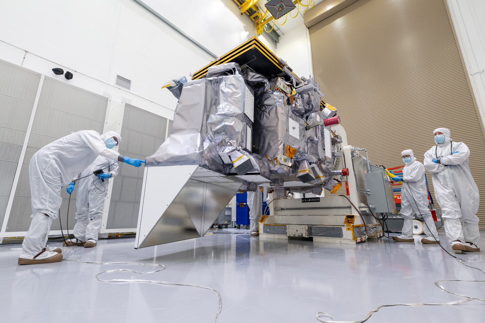
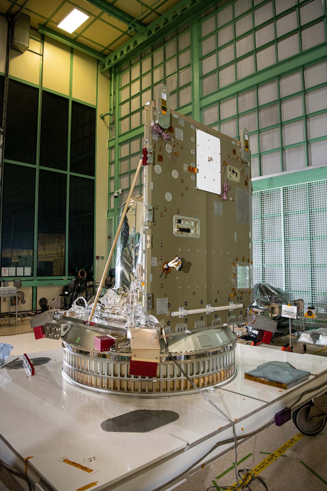
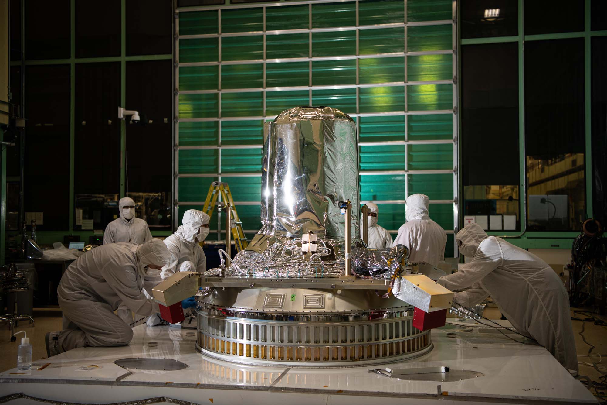
Lift Observatory to Aronson Table, Rotate for Flight Solar Array Wing Installation and Phasing Tests, Lift Back to Observatory Dolly; Lift onto Aronson Table. Credit: NASA
Lift Observatory to Aronson Table, Rotate for Flight Solar Array Wing Installation and Phasing Tests, Lift Back to Observatory Dolly; Lift onto Aronson Table. Credit: NASA
Lift Observatory to Aronson Table, Rotate for Flight Solar Array Wing Installation and Phasing Tests, Lift Back to Observatory Dolly; Lift onto Aronson Table. Credit: NASA
Lift Observatory to Aronson Table, Rotate for Flight Solar Array Wing Installation and Phasing Tests, Lift Back to Observatory Dolly; Lift onto Aronson Table. Credit: NASA
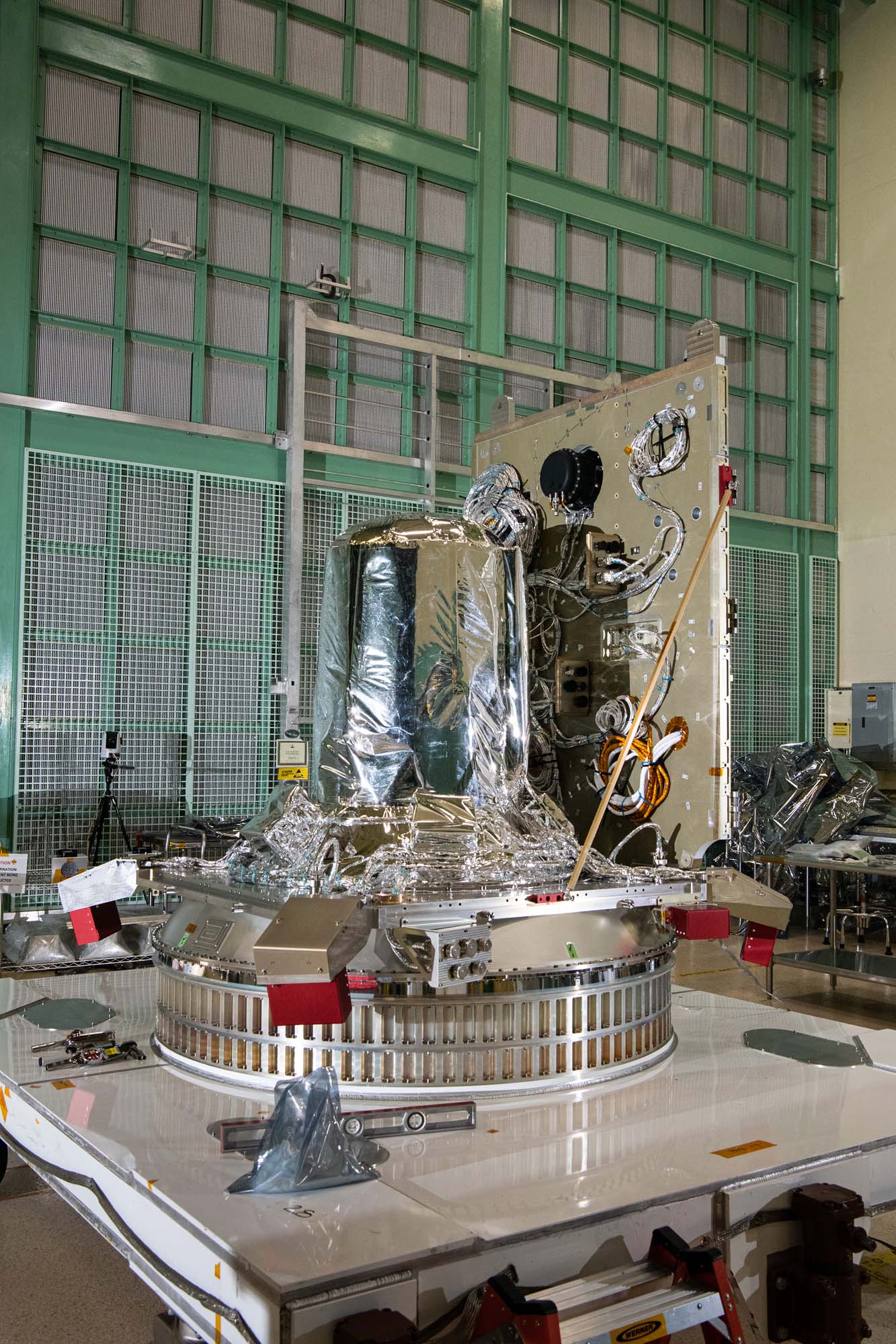
Lift to Aronson Table, Rotate for Flight Solar Array Wing Removal, Lift Back to Observatory Dolly; Cleaning of Aronson table. Credit: NASA
Final configuration in chamber prior to door closing & Hot Soak; Solar Array engineering test unit Wing Pop and Catch Thermal Vacuum Test. Credit: NASA
Final configuration in chamber prior to door closing & Hot Soak; Solar Array engineering test unit Wing Pop and Catch Thermal Vacuum Test. Credit: NASA
Solar Array enginnering test unit Wing Pop and Catch Thermal Vacuum Test; Replace NEAs, Preload, tethers, after hot pop before Cold Pop and catch Credit: NASA
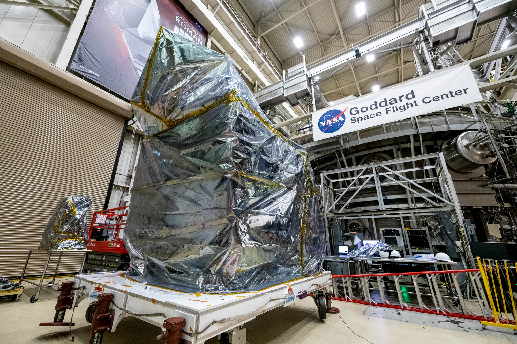
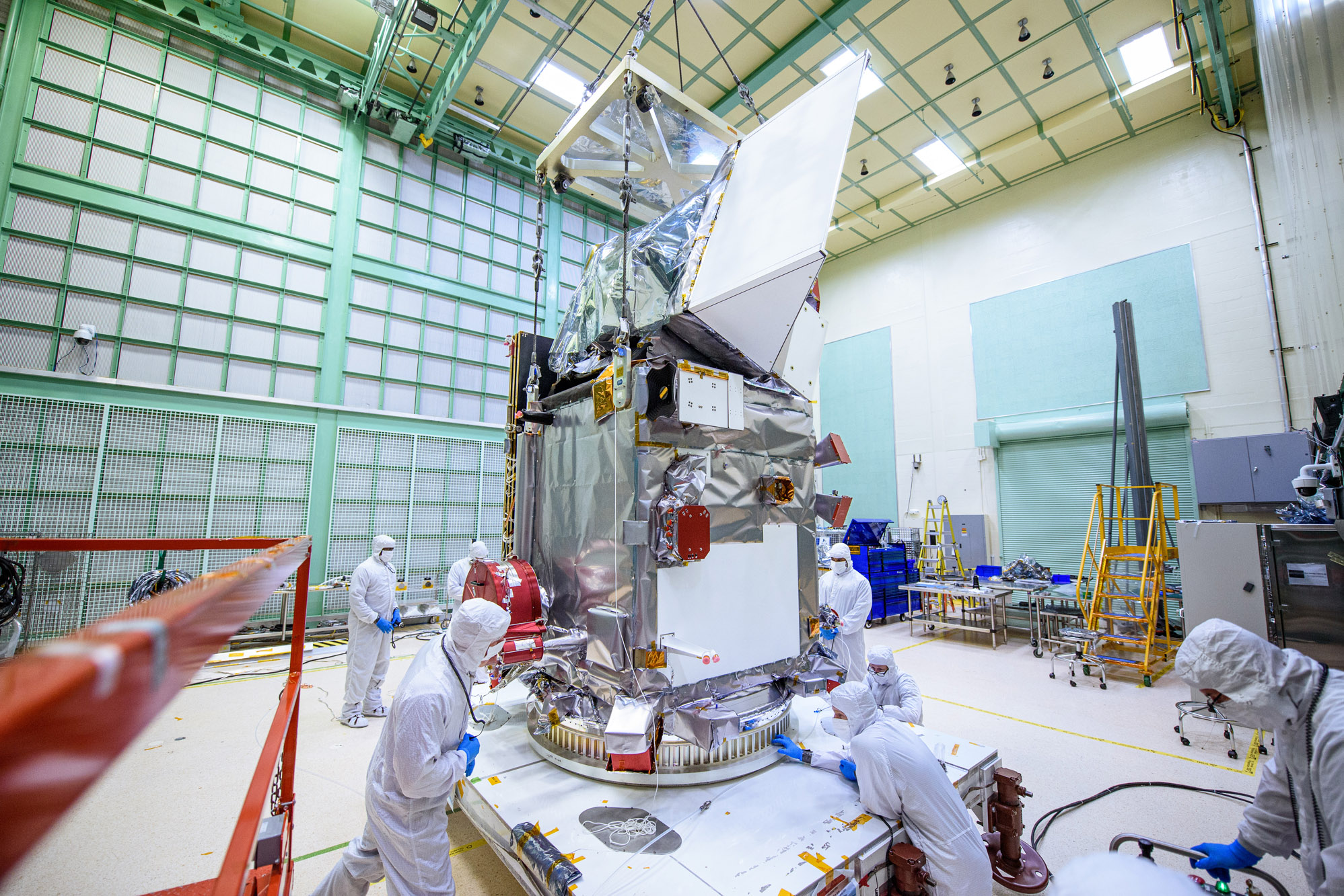
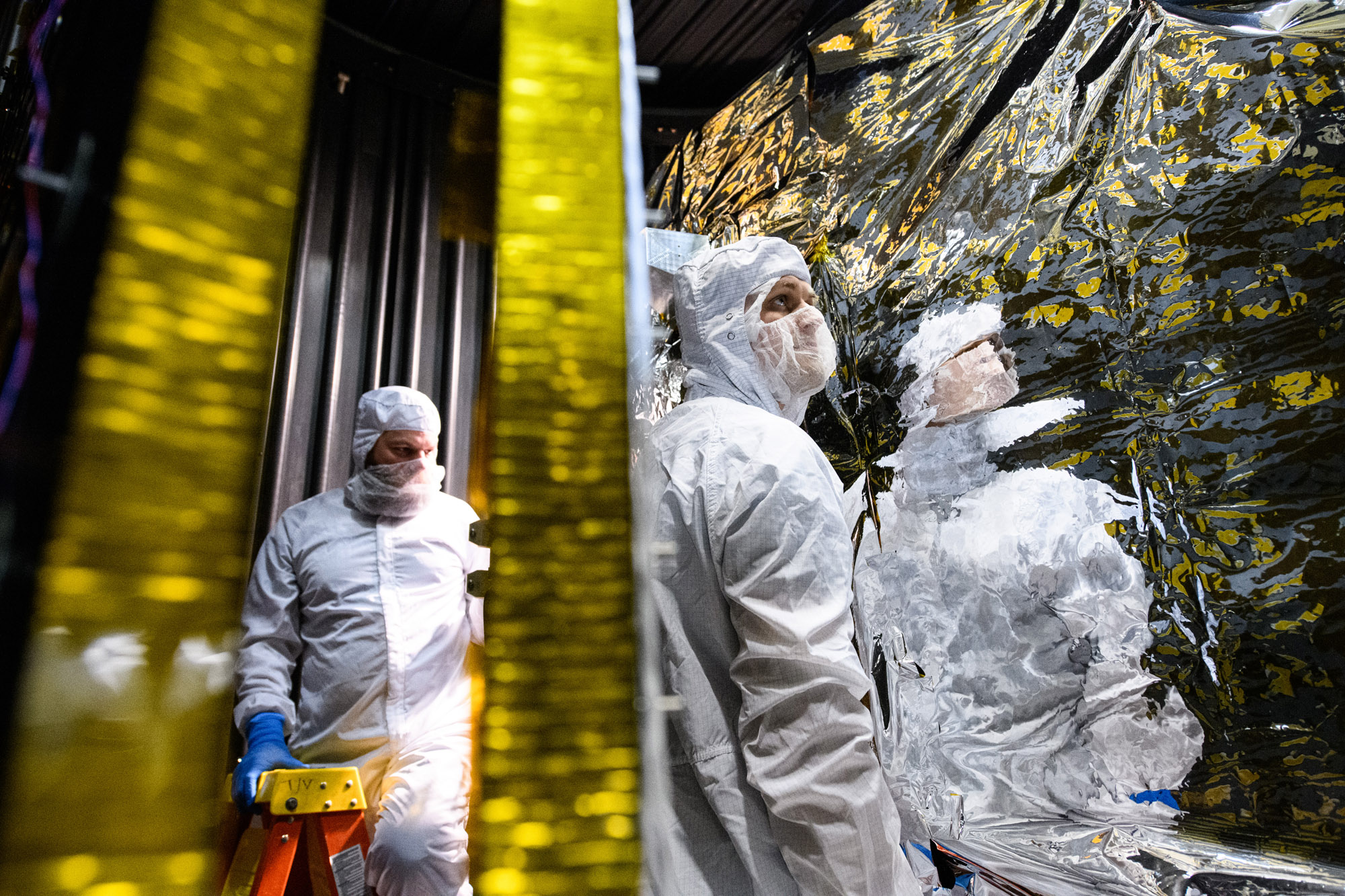
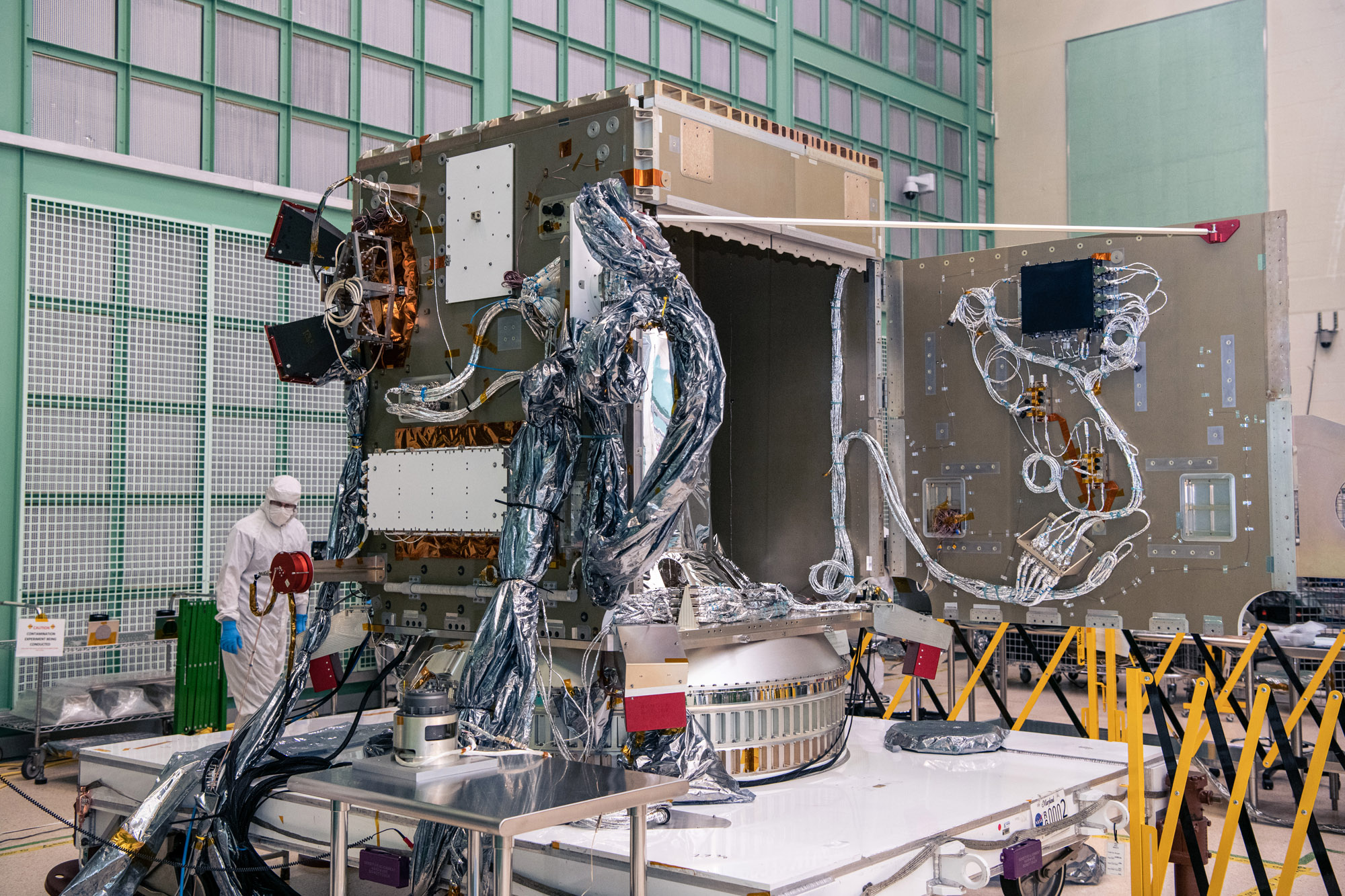
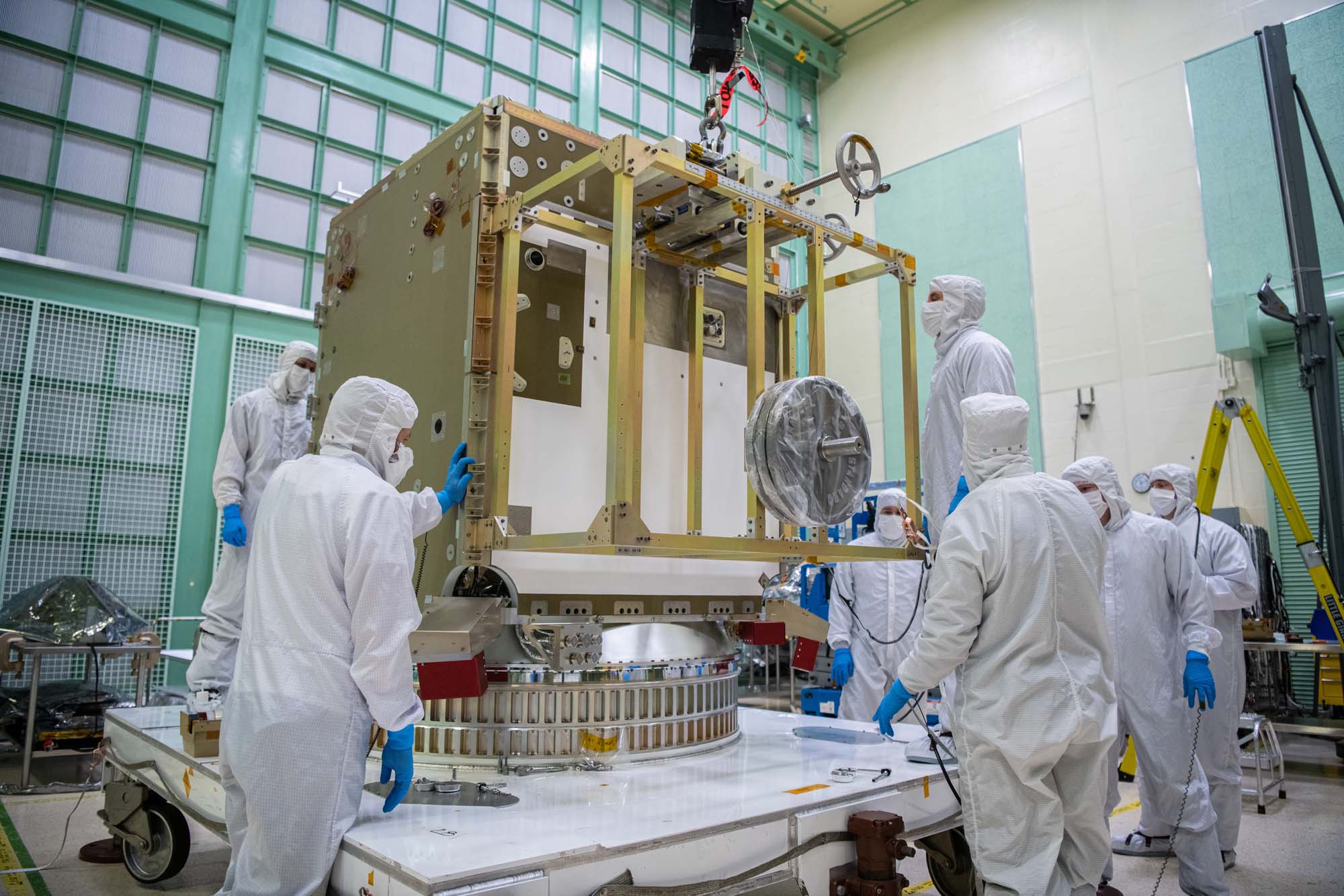
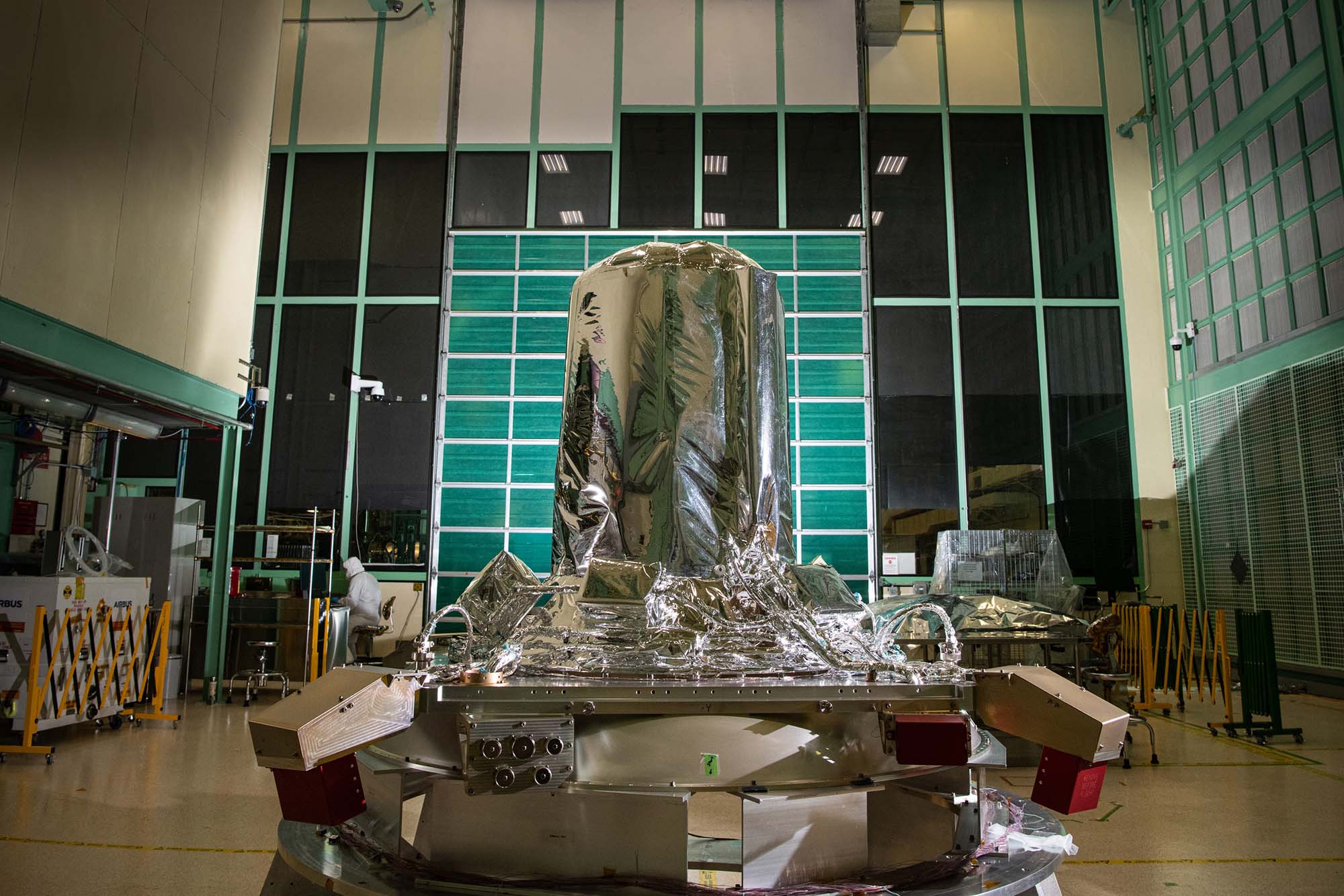
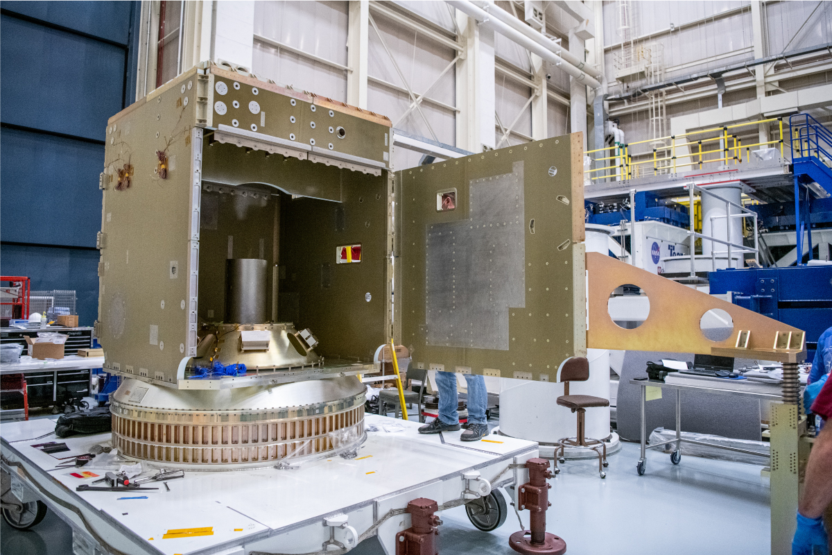
PACE Observatory Glamour Photos in electromagnetic interference (EMI) Chamber; Move Observatory to EMI: Install bagging standoffs, bag the Observatory, and move to EMI test facility. Credit: NASA
Partial +Y Panel Opening; Open and Close the +Y Panel. Credit: NASA
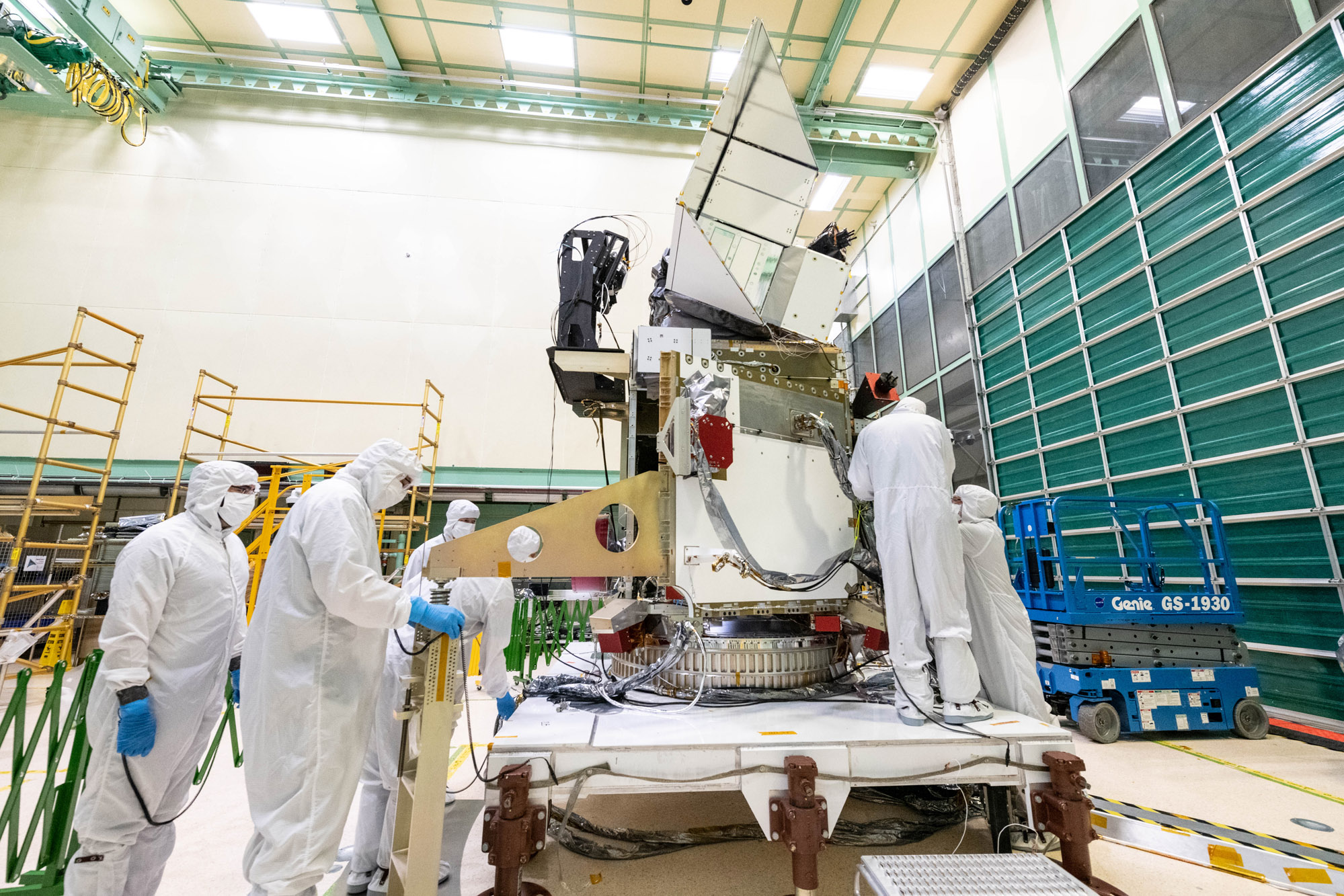
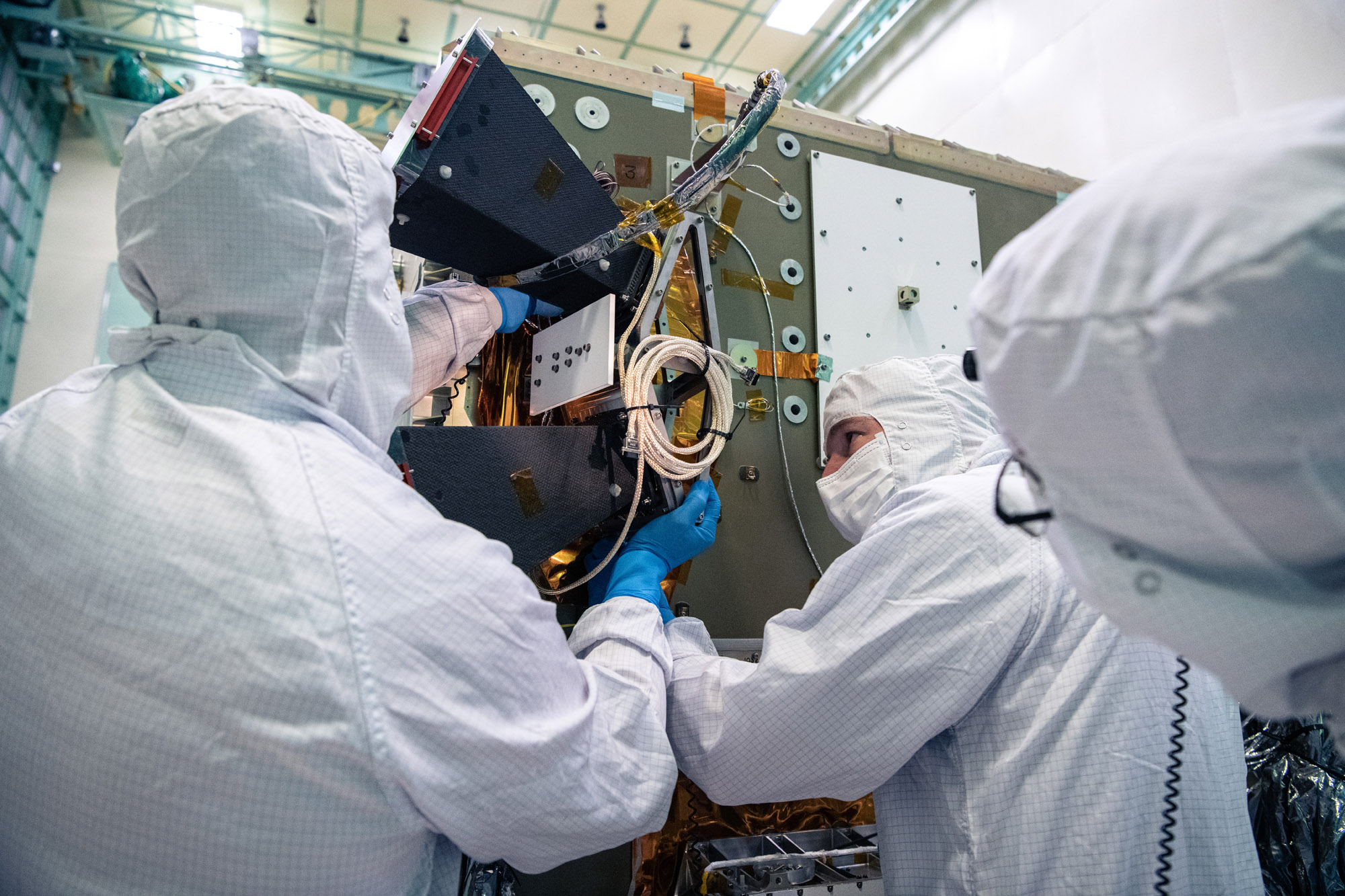
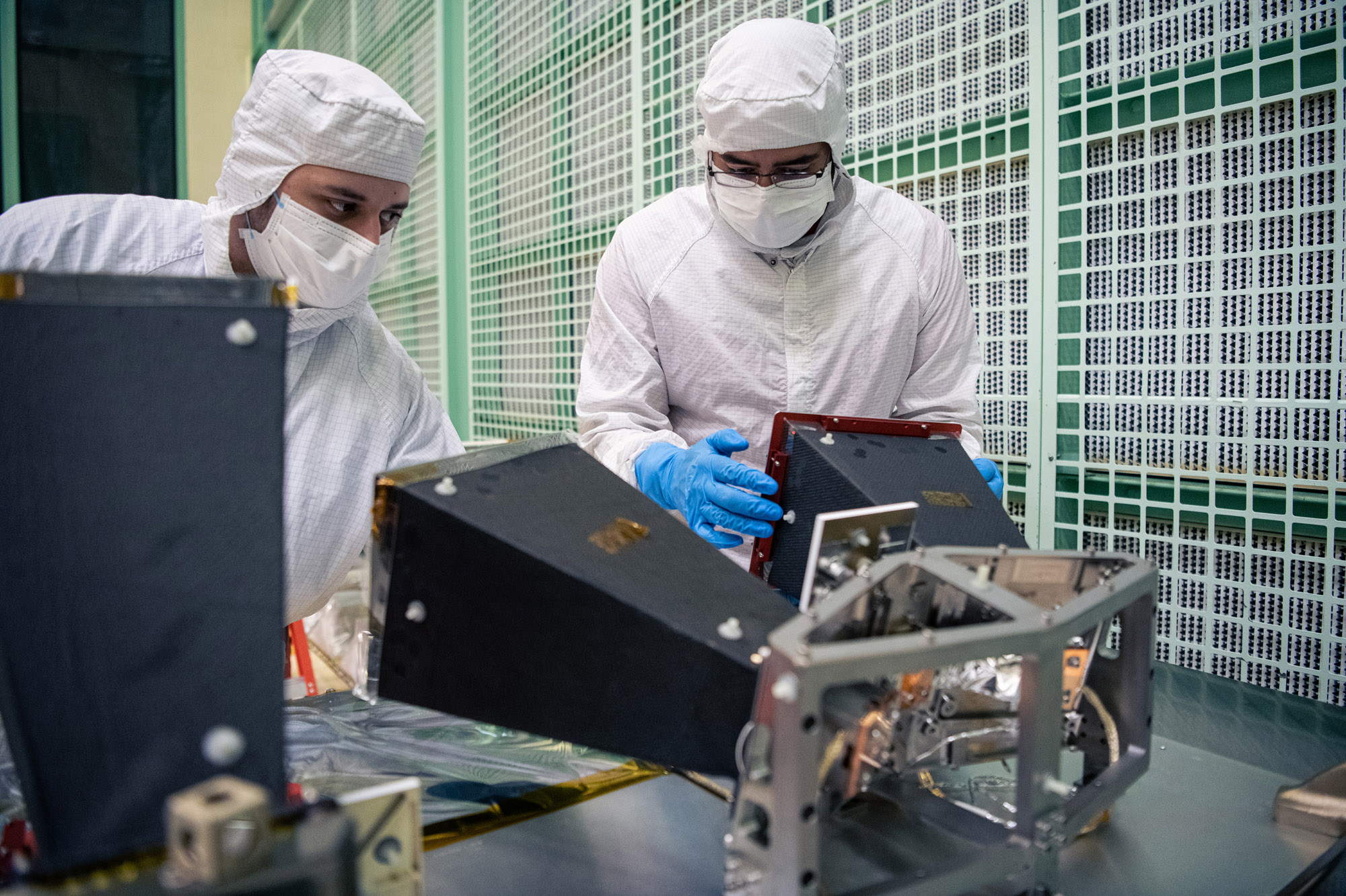
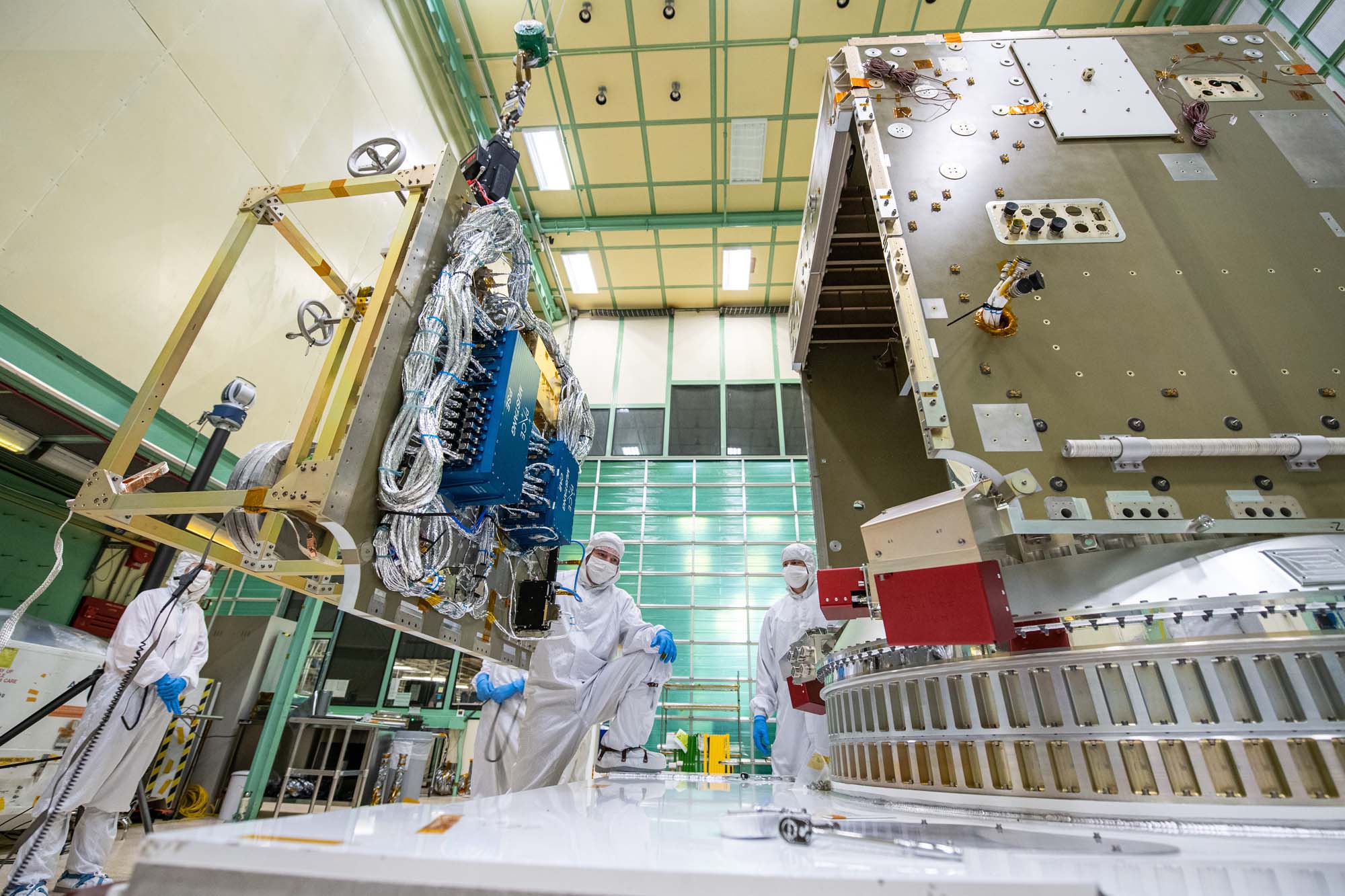
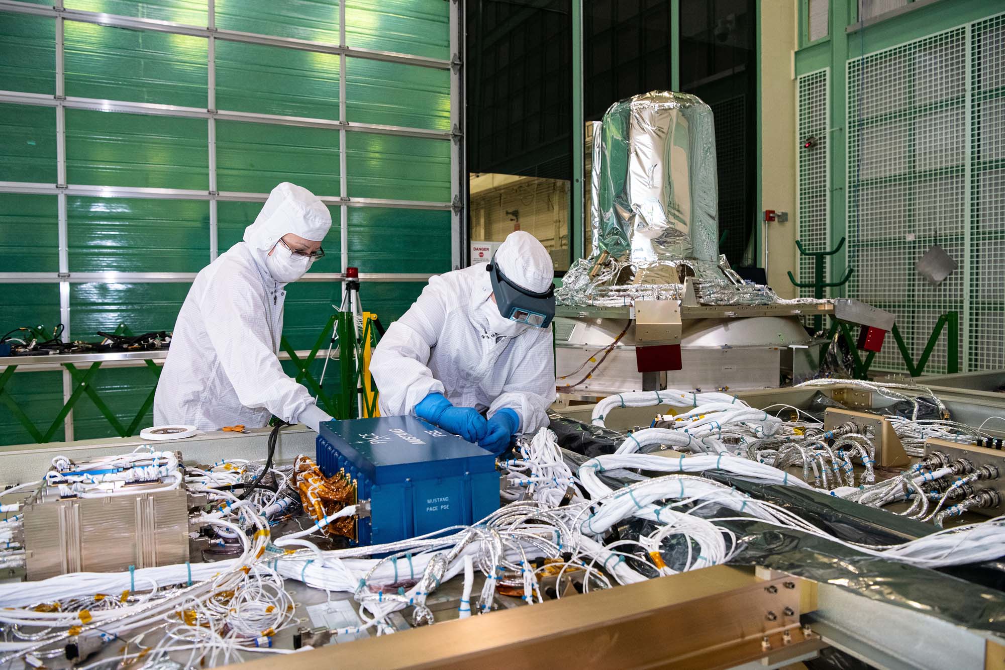
PACE Mechanical Team with the spacecraft. Credit: NASA
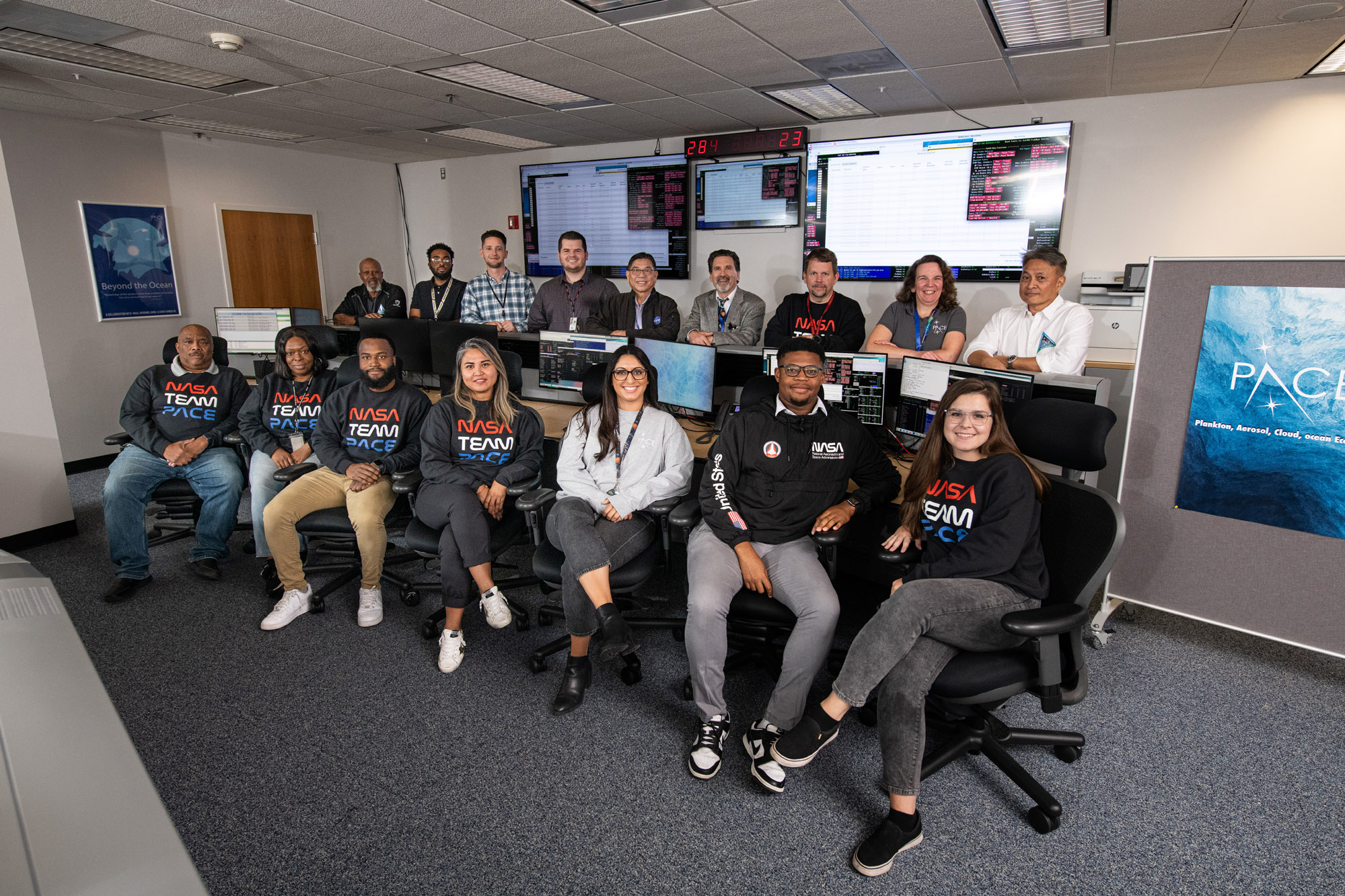
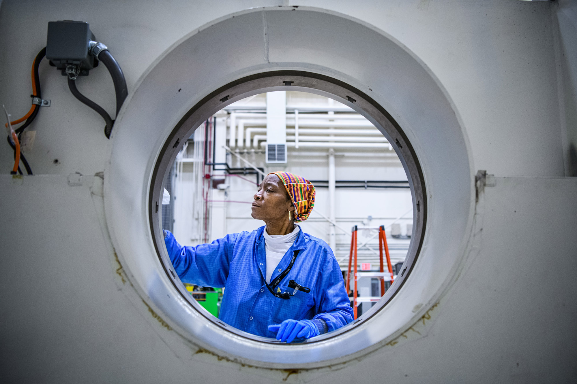
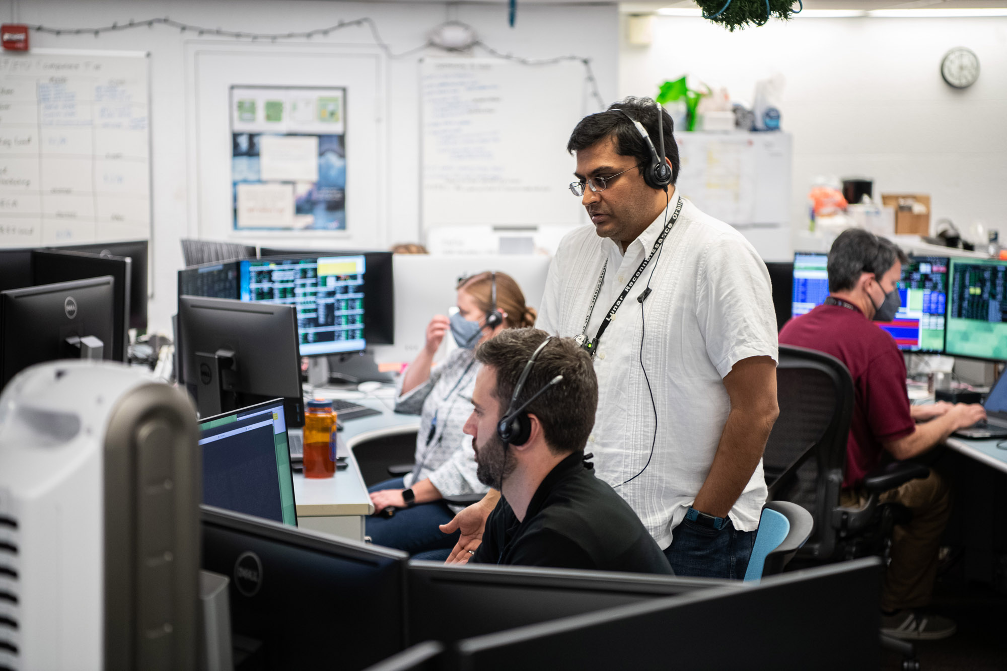
Candid and portrait photos of the PACE Mission Operations Center. Credit: NASA
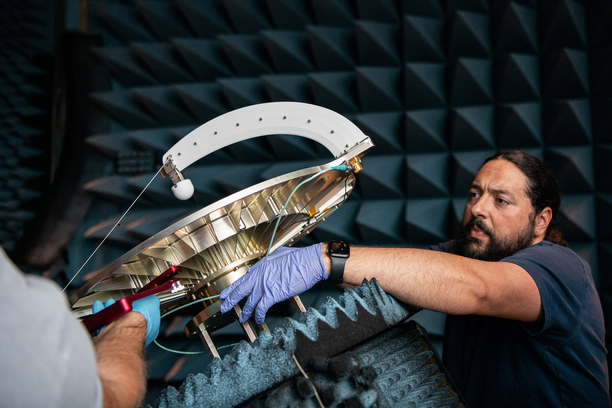
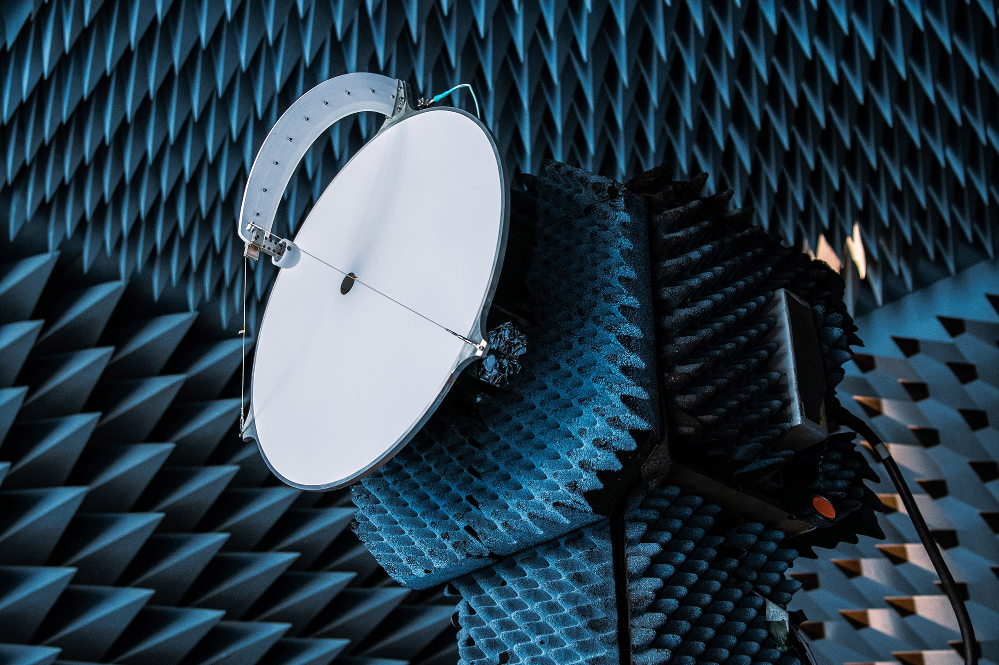
Install Earth Coverage Antenna (ECA) and Temporary Install Waveguides to PACE Spacecraft BUS; ECA and Hat Coupler installed on Spacecraft. Credit: NASA
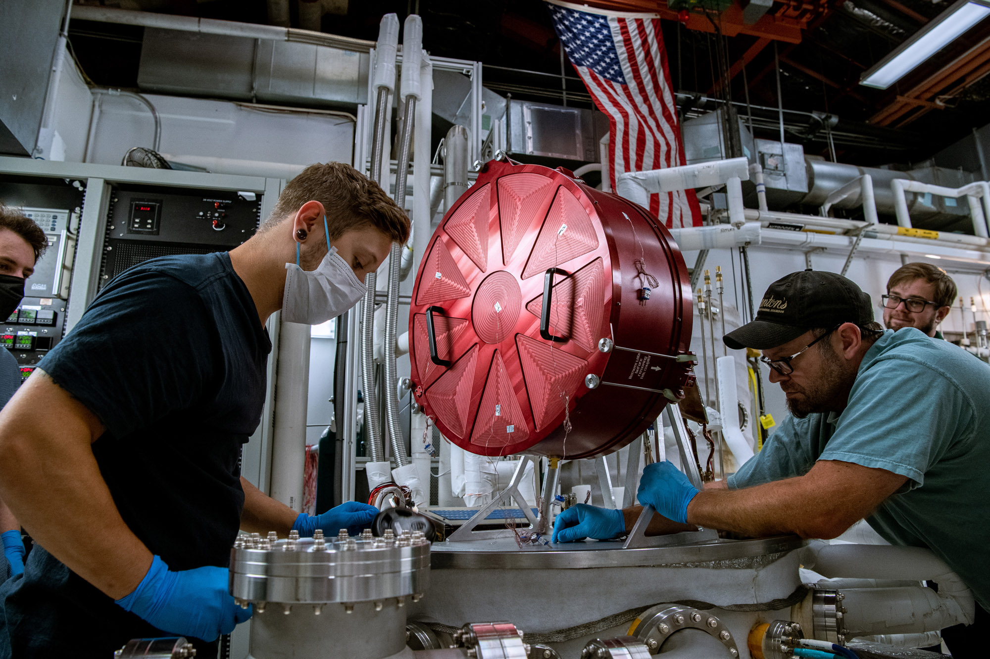
The red object is known as a "hat," which shields PACE's Earth coverage antenna and prevents emission of radiation during testing. Credit: Henry, Dennis (Denny)
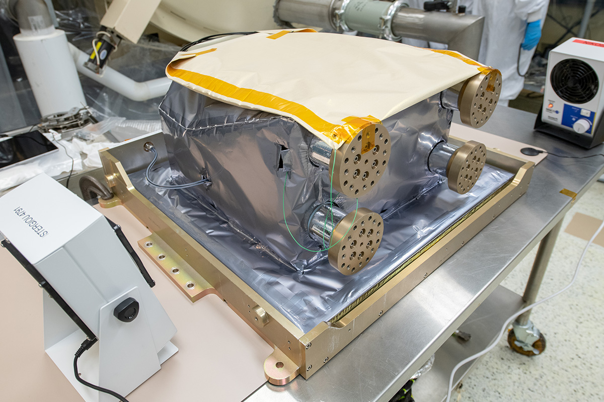
Thermal vacuum test of Ka-band Earth coverage antenna. Credit: Henry, Dennis (Denny)
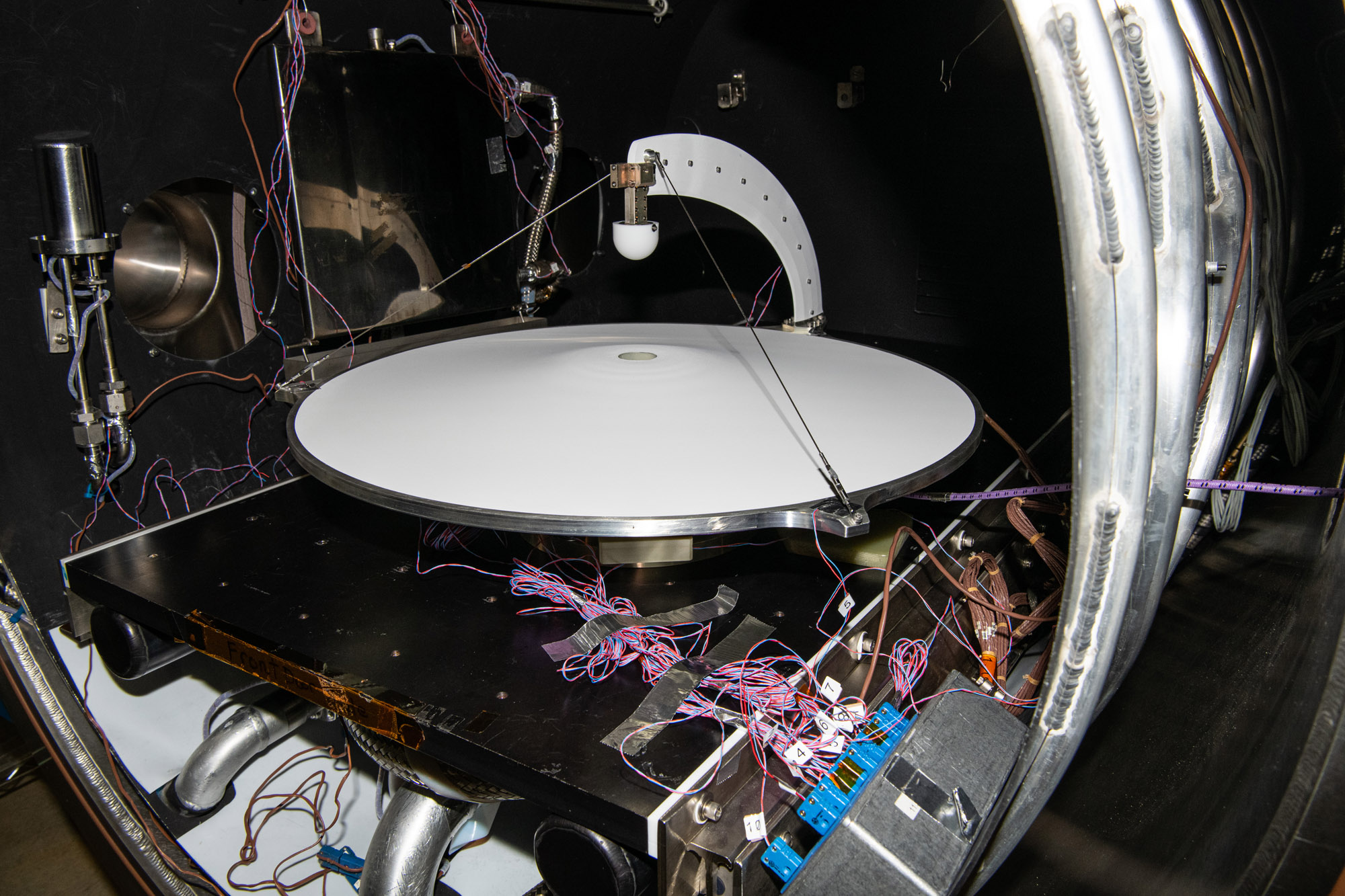
Thermal vacuum test of Ka-band Earth coverage antenna. Credit: Henry, Dennis (Denny)
Radiofrequency testing setup after spacecraft vibration test. Credit: Henry, Dennis (Denny)
Setting up for radiofrequency testing. Credit: Henry, Dennis (Denny)
PACE Control room. Credit: Henry, Dennis (Denny)
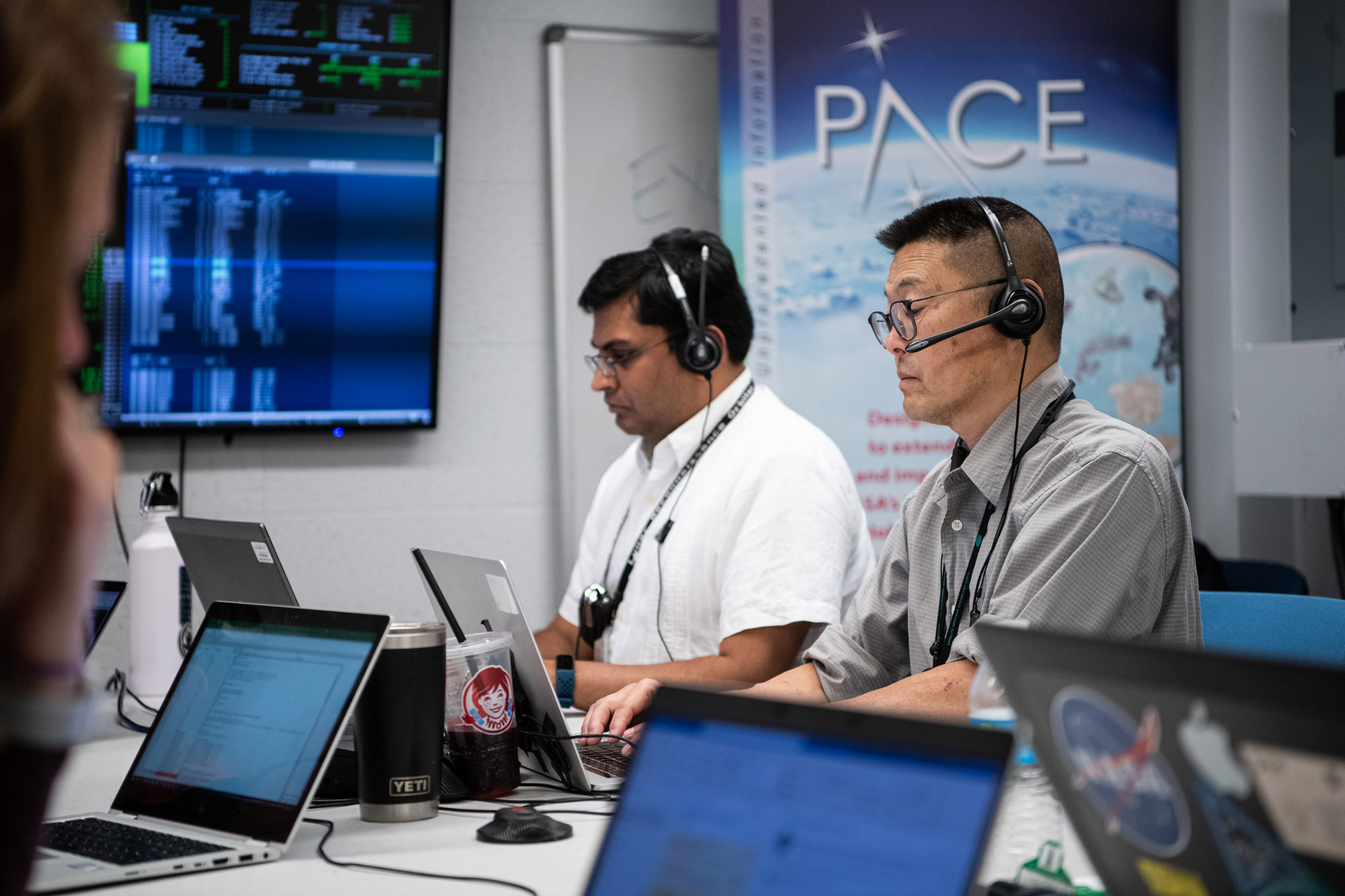
PACE Control room. Credit: Henry, Dennis (Denny)
Lifting Structural Verification Unit out of chamber for the Sine Vibration Test. Credit: Henry, Dennis (Denny)

Installing Low Gain Antenna on PACE Spacecraft bus. Credit: Henry, Dennis (Denny)
Aligning the solar arrays and Structural Verification Unit to perform electrical tests. Credit: Lambert, Barbara
Lifting PACE Structural Verification Unit onto Aronson Table for engineering tests. Credit: Lambert, Barbara
Opened -Y Panel. Credit: Henry, Dennis (Denny)
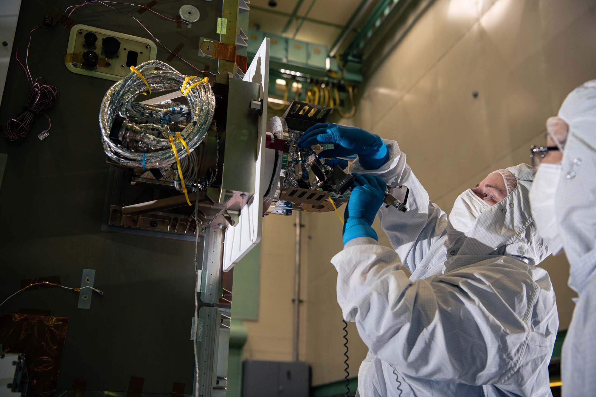
Installing bus Star Tracker Sensor on the PACE -Z Panel. Credit: Henry, Dennis (Denny)
Installing the bus Star Tracker Sensor on the -Z Panel. Credit: Lambert, Barbara
Installing Star Tracker Sensor on the -Z Panel. Credit: Henry, Dennis (Denny)
Inspecting the PACE Star Tracker Sensor. Credit: Lambert, Barbara
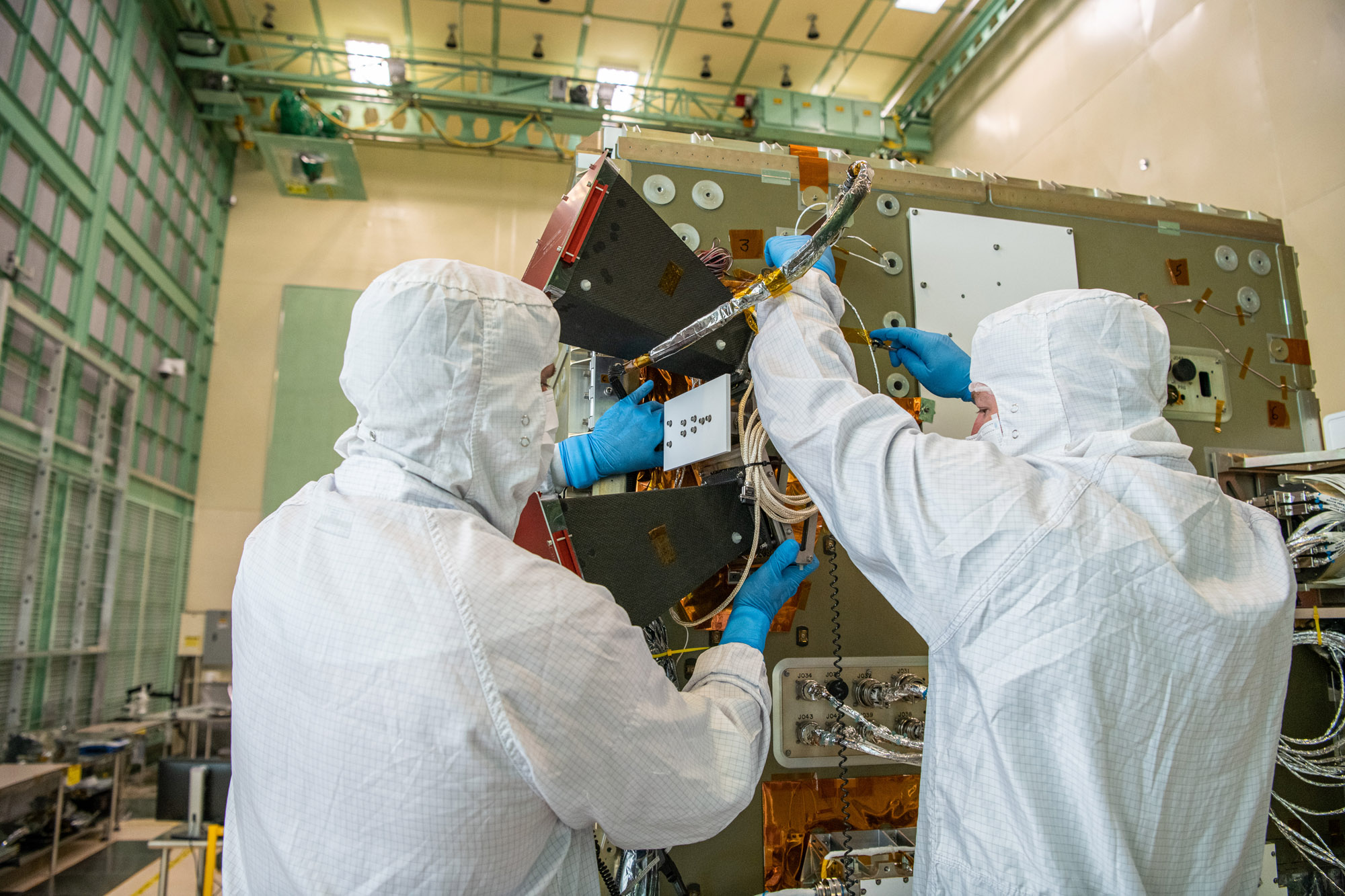
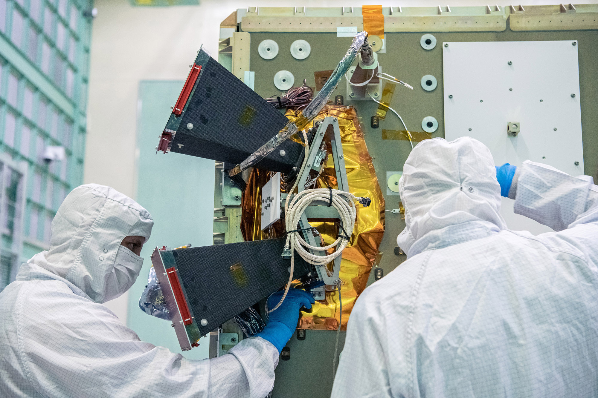
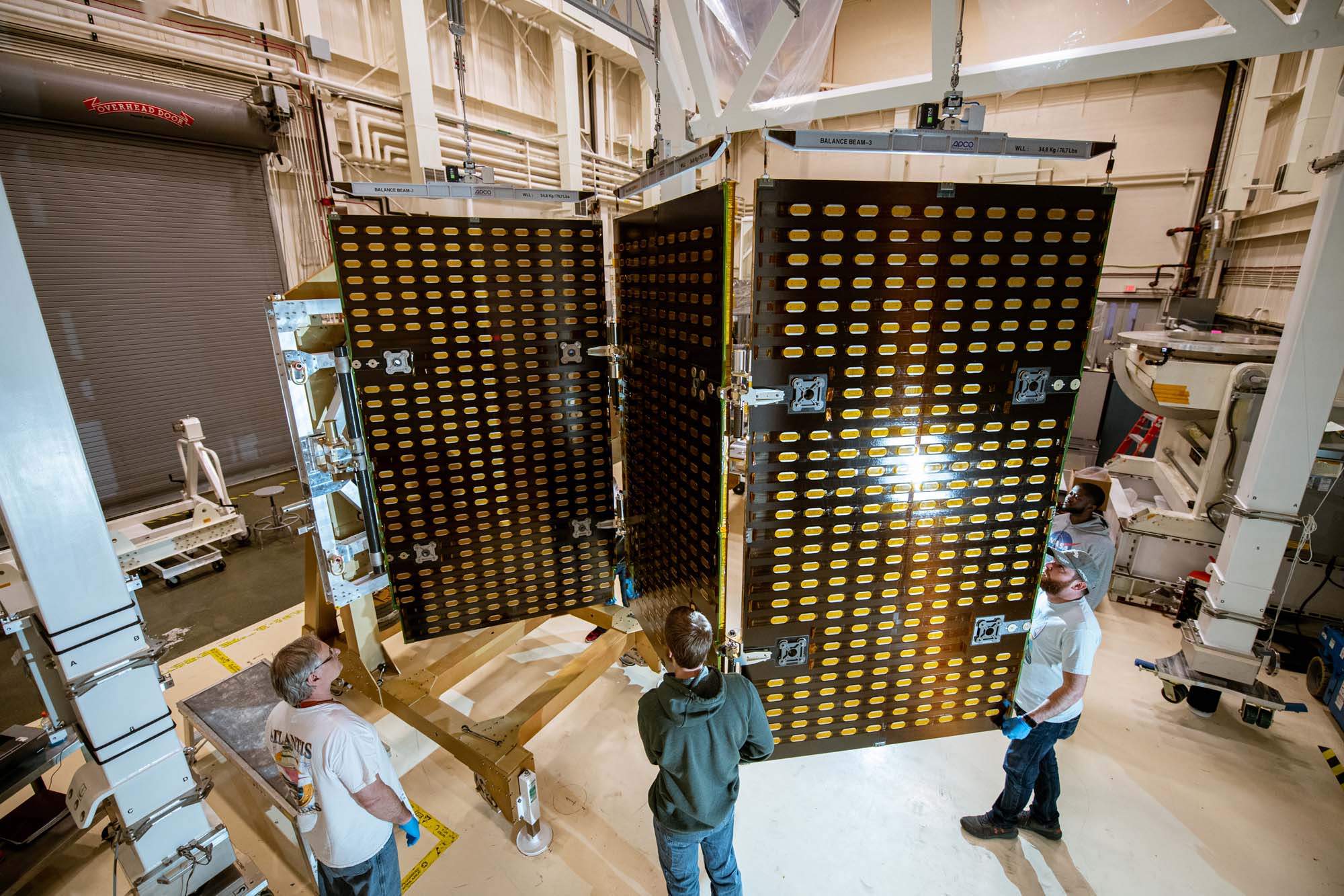
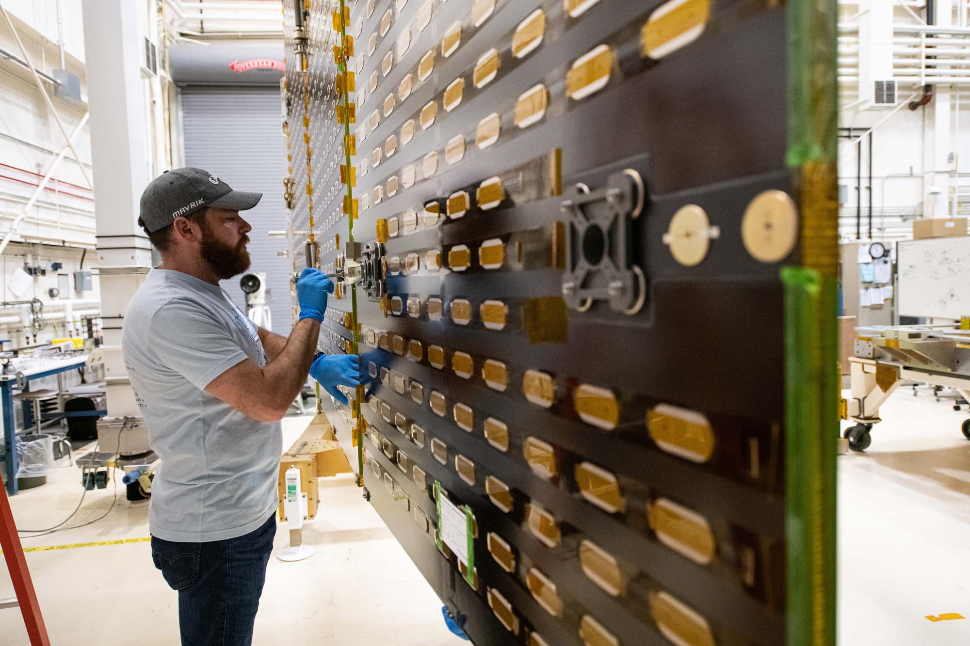
Inspection and electrical testing of PACE Flight Solar Array Panels. Credit: Henry, Dennis (Denny)
Alignment team working on the PACE spacecraft. Credit: Henry, Dennis (Denny)
Alignment team working on the PACE spacecraft. Credit: Henry, Dennis (Denny)
Testing solar array drive assembly on PACE spacecraft bus. Credit: Henry, Dennis (Denny)
Installing the solar array drive assembly on the PACE spacecraft bus. Credit: Lambert, Barbara
Overall photos of spacecraft after solar array drive assembly install. Credit: Lambert, Barbara
PACE spacecraft team checking alignment data. Credit: Henry, Dennis (Denny)
PACE engineering test unit for solar array drive assembly wing setup. Credit: Henry, Dennis (Denny)
PACE engineering test unit for solar array drive assembly walkouts on the gantry. Credit: Henry, Dennis (Denny)
Tightening bolts on the PACE engineering test unit solar array drive assemblies wing setup. Credit: Lambert, Barbara
Measuring PACE engineering test unit solar array drive assemblies wing setup. Credit: Lambert, Barbara
Carlos Duran-Aviles with the PACE reaction wheel assembly. Credit: Lambert, Barbara
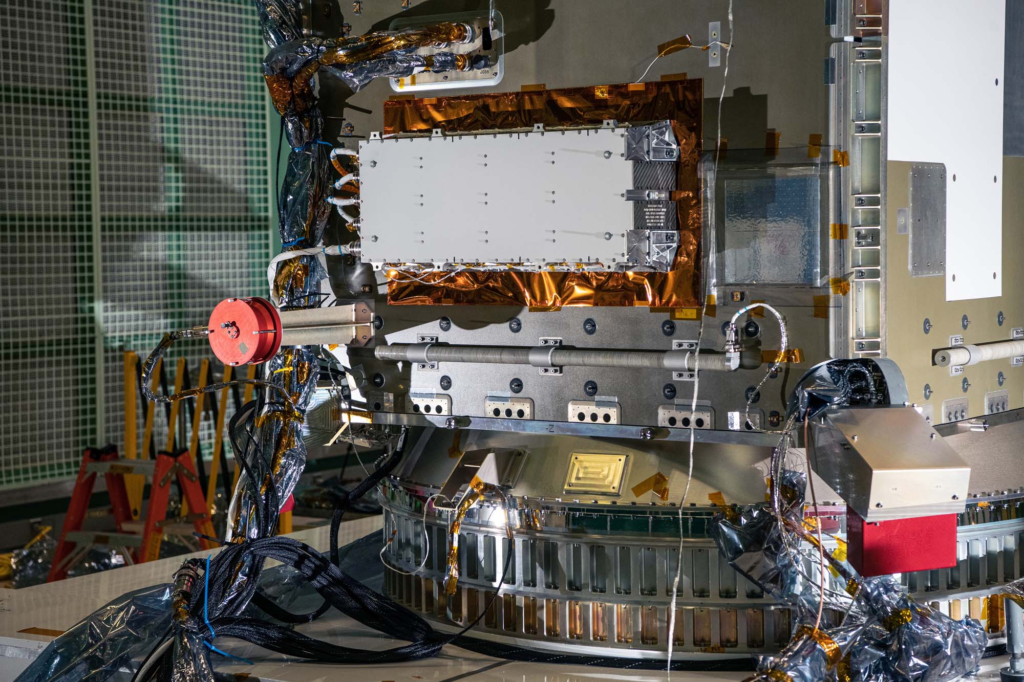
The Optical Module (OM) and the Flight Instrument Deck Structure (IDS) are integrated together, creating the Flight Ocean Color Instrument. Credit: Stover, Desiree
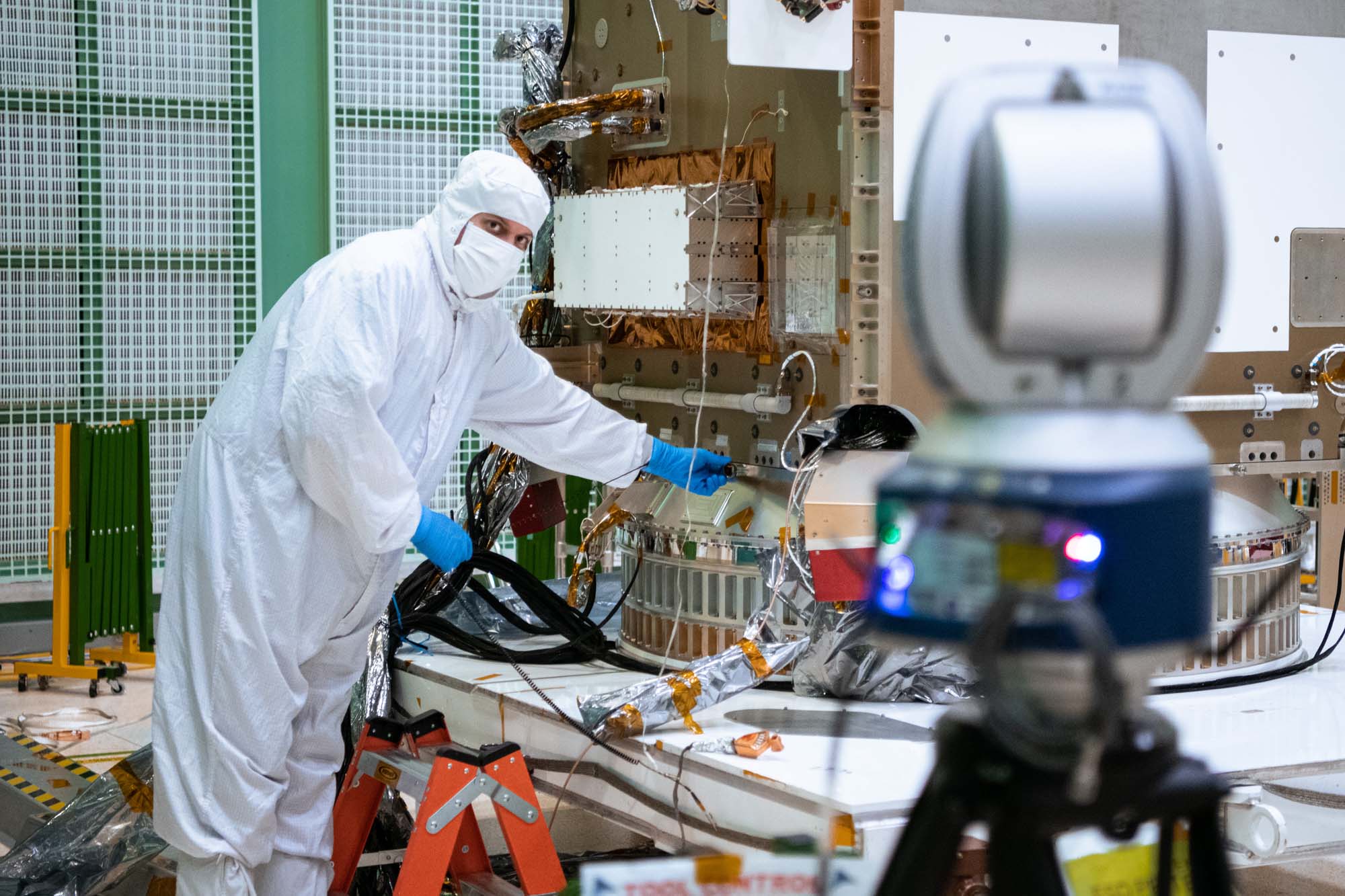
Performing component functional testing on the PACE spacecraft. Credit: Lambert, Barbara
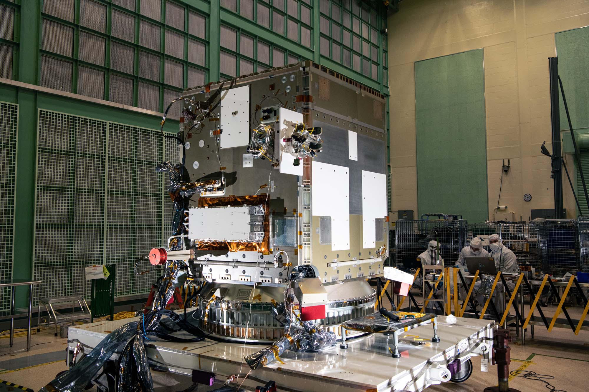
Members of PACE spacecraft integration and test team. Credit: Lambert, Barbara
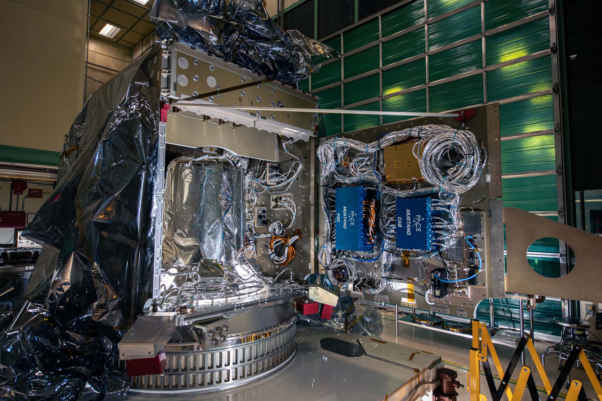
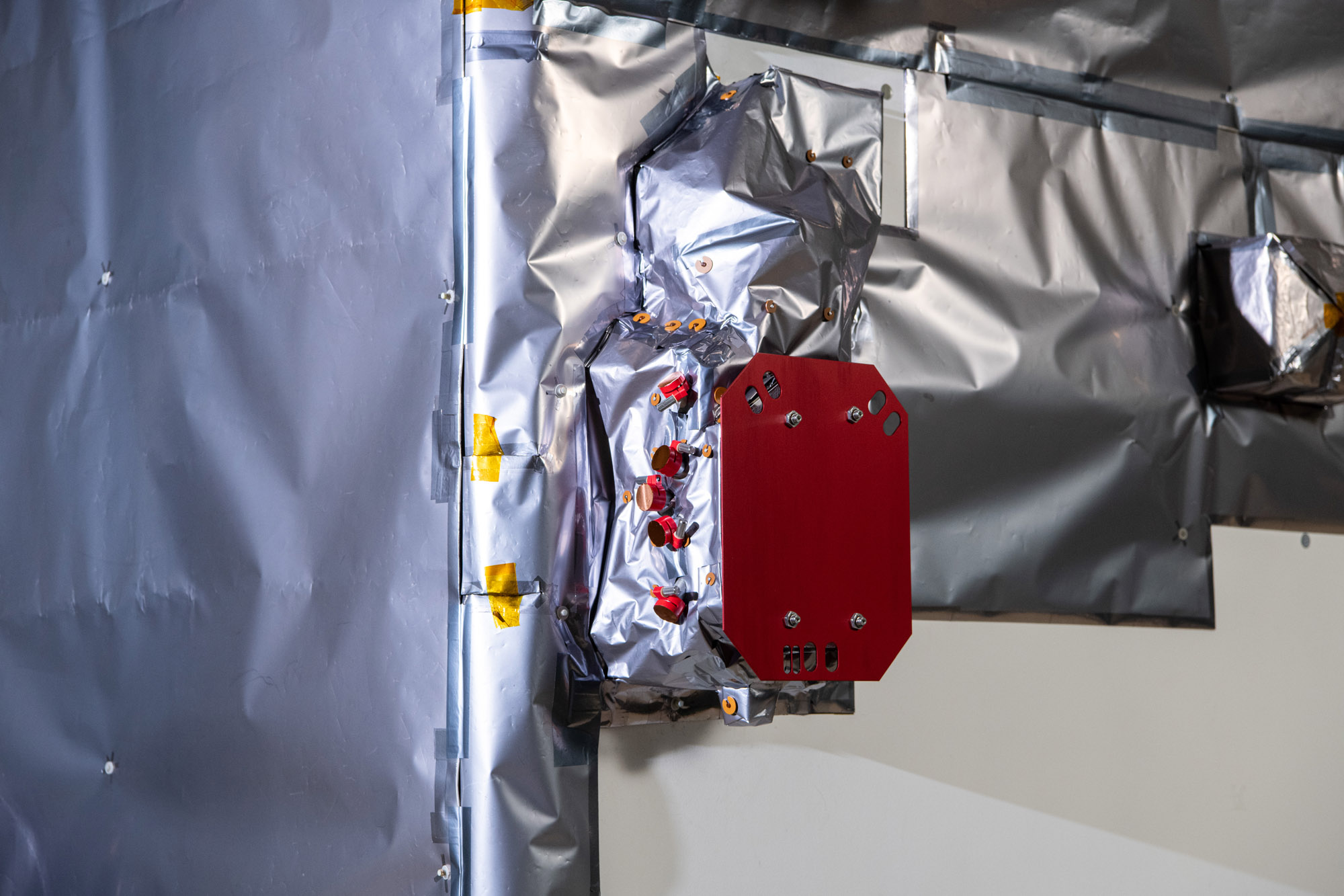
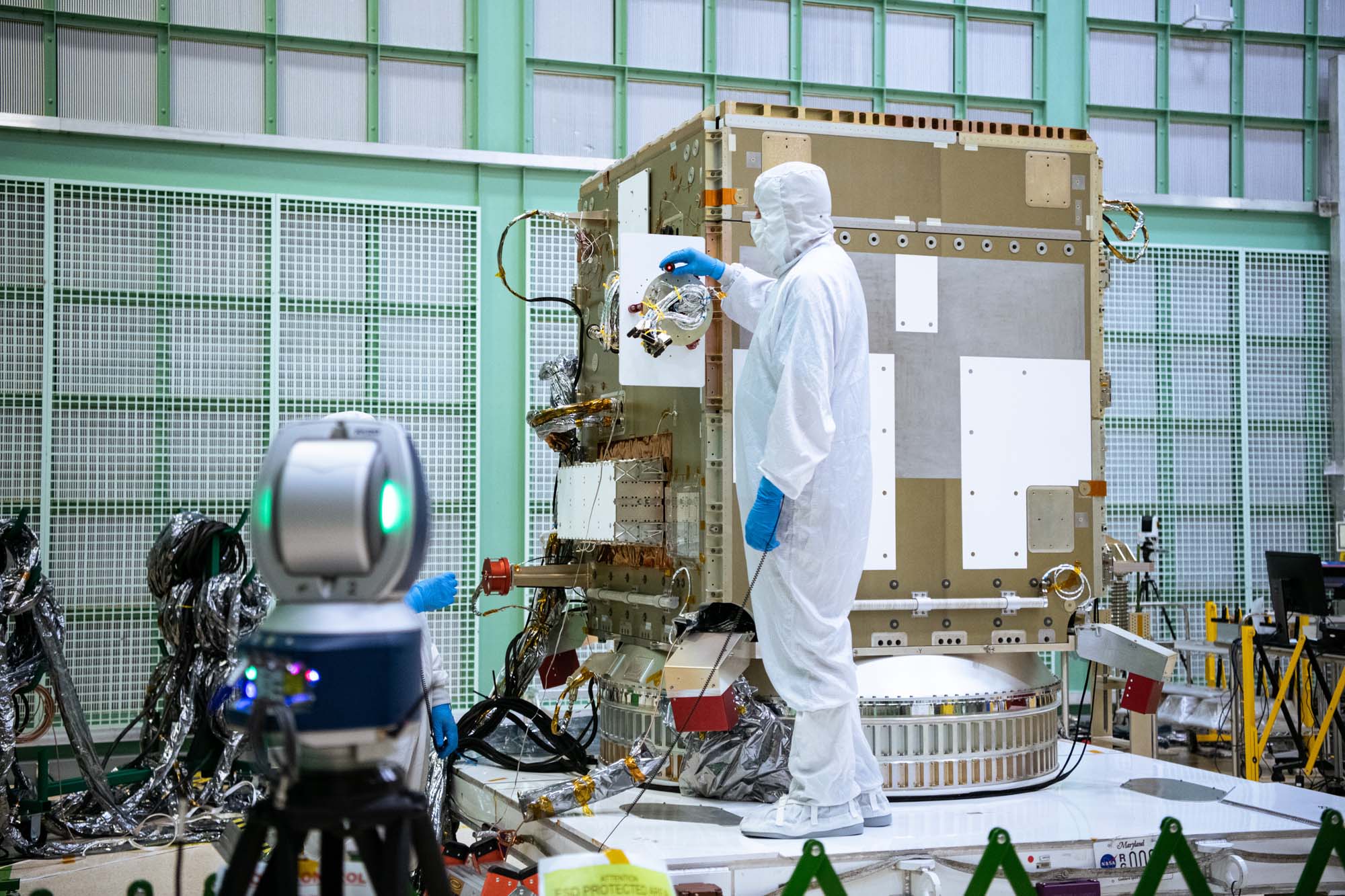
Open panel (-Y) on spacecraft bus. Blue electronics boxes are for power system and attitude control electronics. Credit: Lambert, Barbara
Installing qual battery on flight spacecraft bus. Credit: Henry, Dennis (Denny)
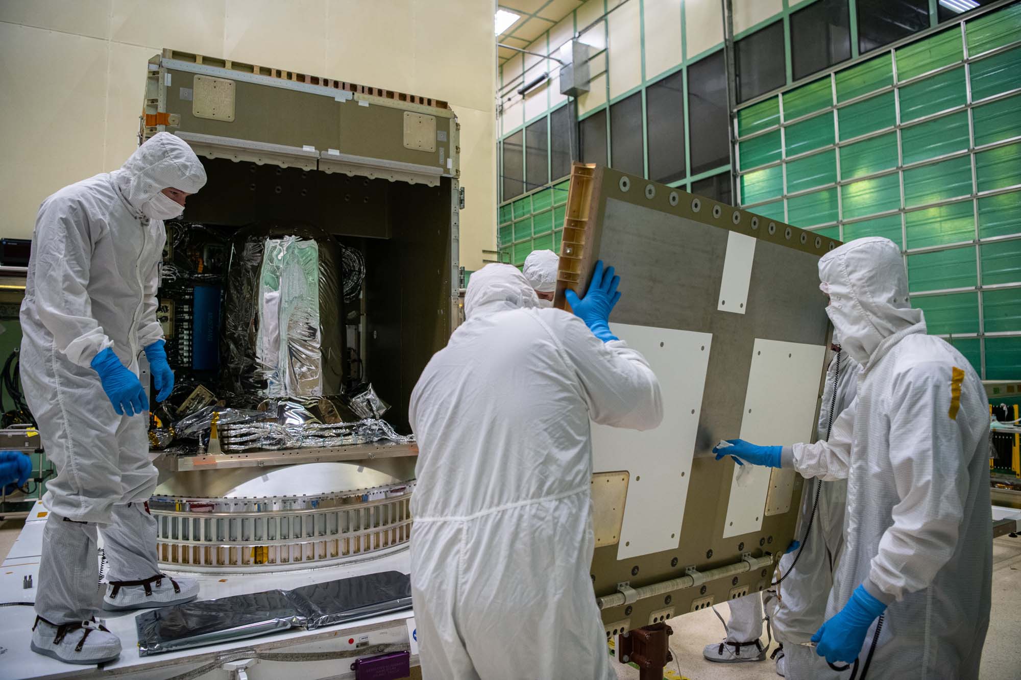
Panel (-Y) being installed on the spacecraft structure. Credit: Henry, Dennis (Denny)
Panel (-Y) being installed on the spacecraft structure. Credit: Henry, Dennis (Denny)
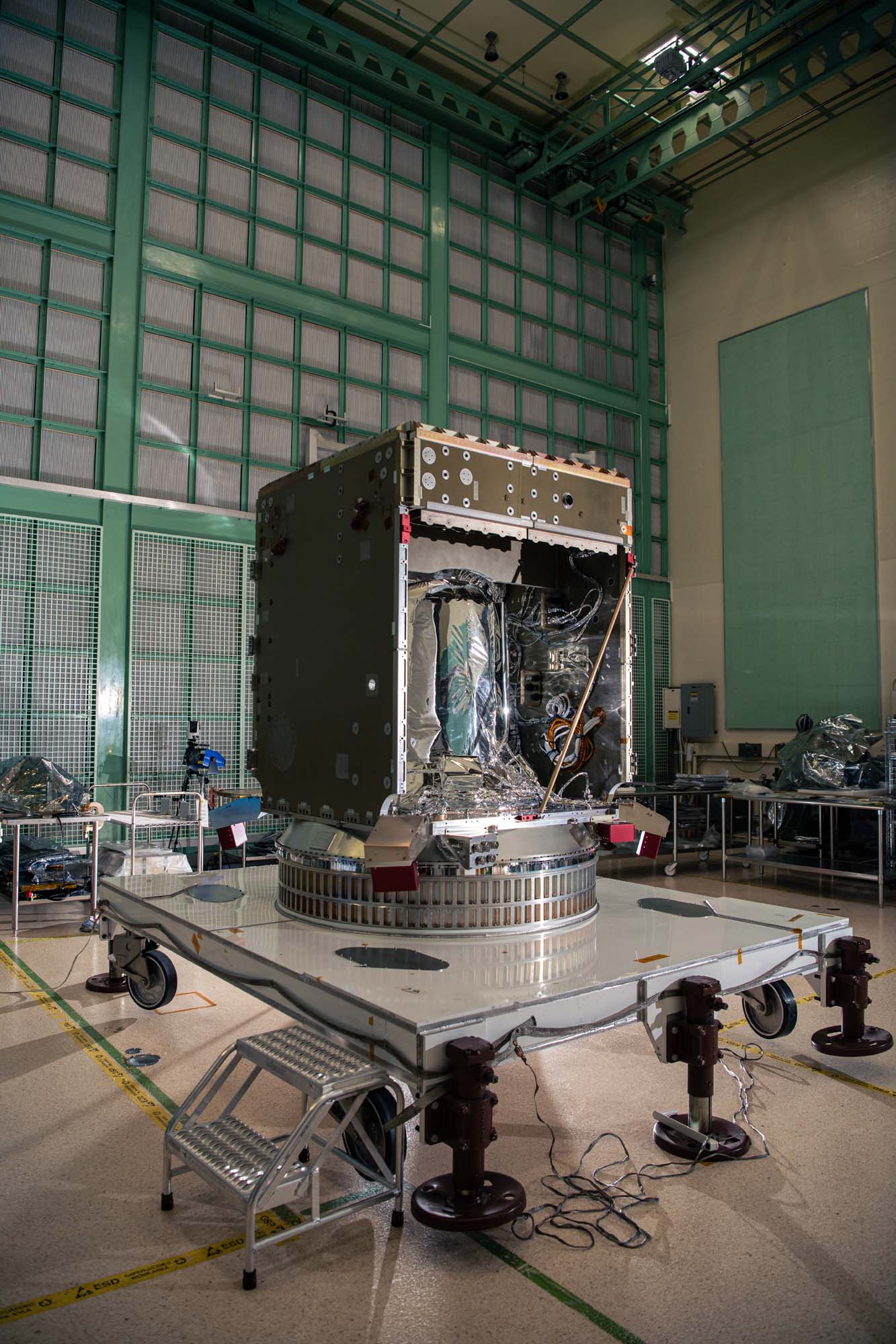
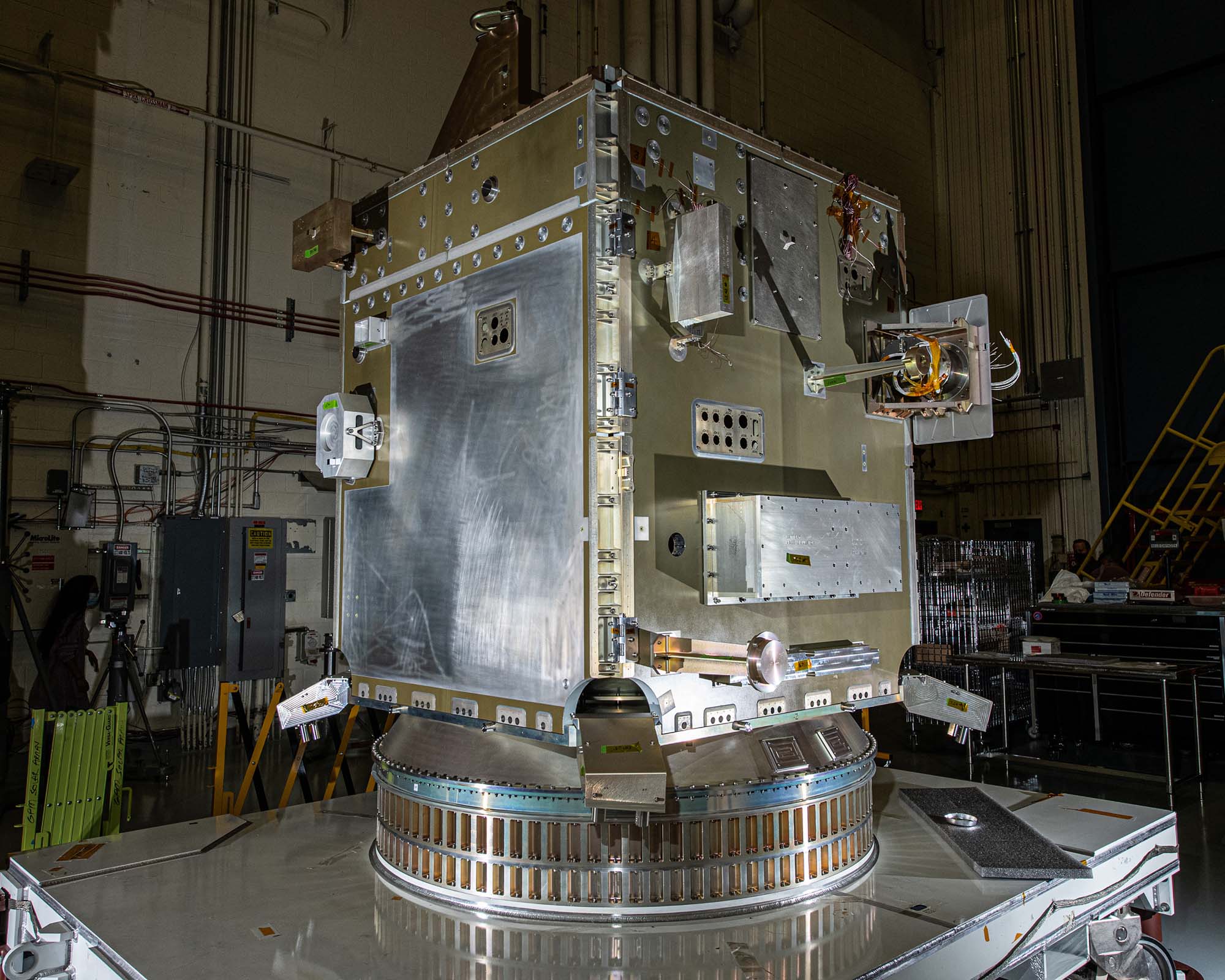
PACE spacecraft bus structure. Credit: Henry, Dennis (Denny)
Assembling PACE spacecraft bus structure. Credit: Henry, Dennis (Denny)
Panel (+Y) installed on the PACE spacecraft bus. Credit: Henry, Dennis (Denny)
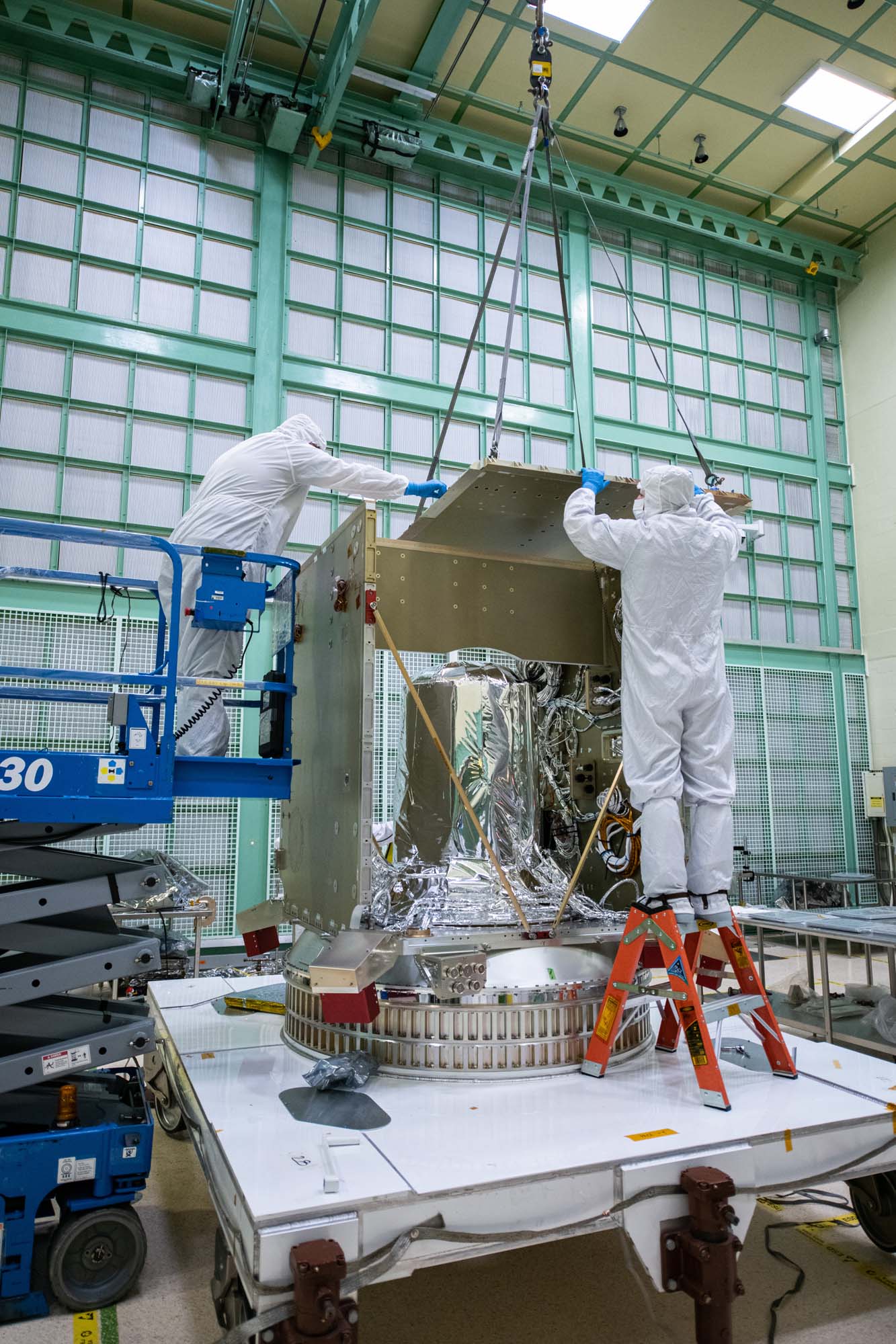
Installing panel (+Y) on the PACE spacecraft bus. Credit: Henry, Dennis (Denny)
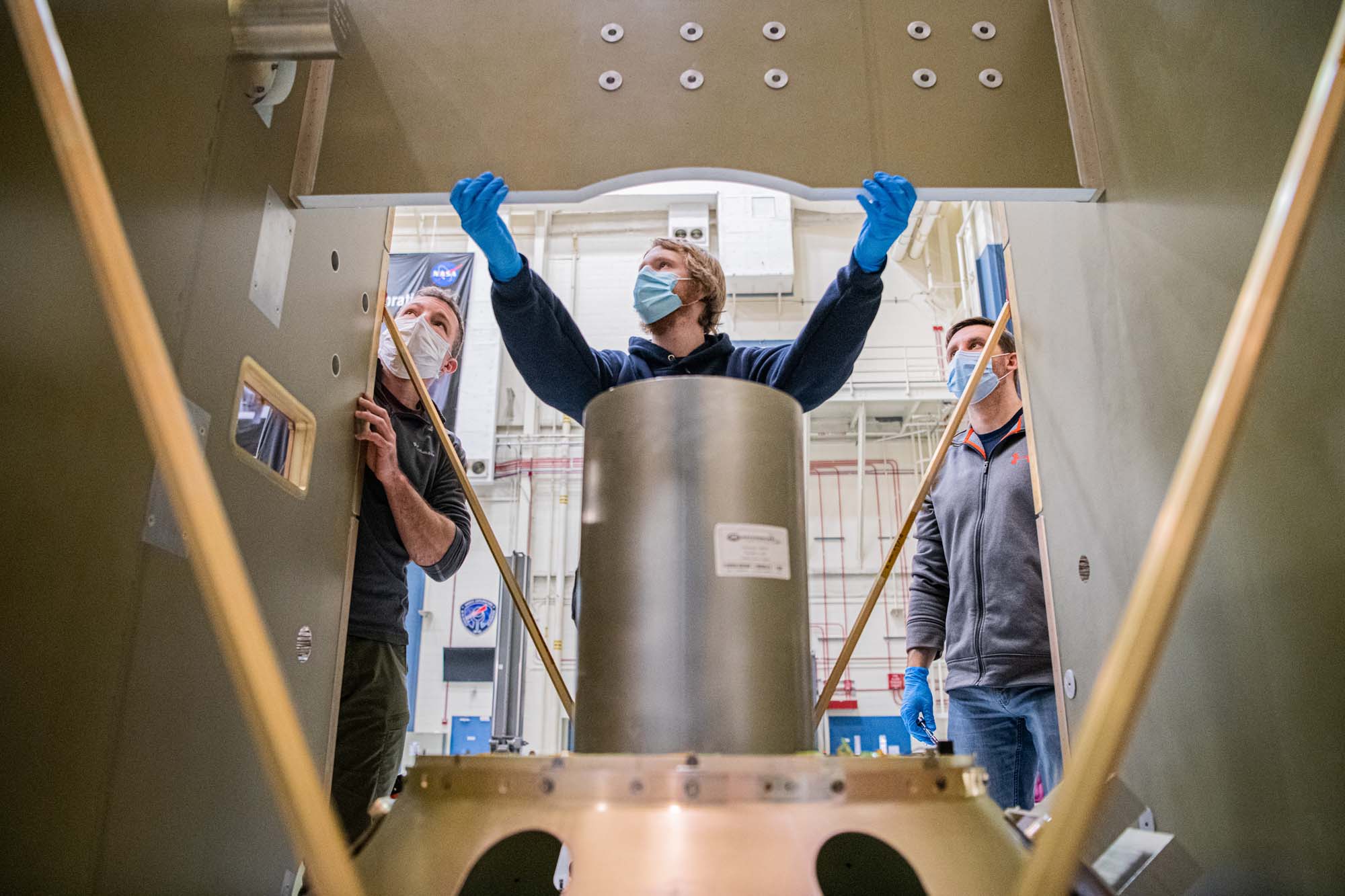
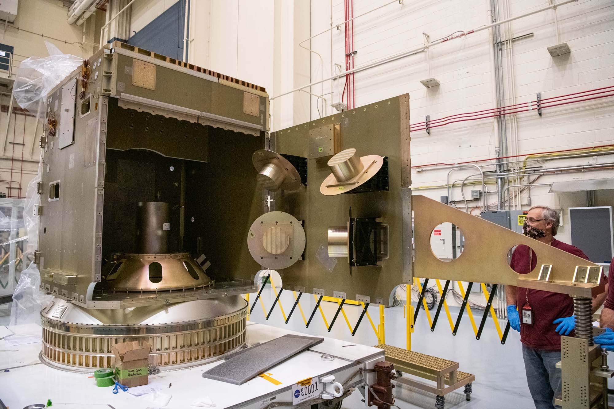
Assembling PACE spacecraft bus structure. Propulsion tank is in the middle. Credit: Henry, Dennis (Denny)
View inside the PACE spacecraft bus structure. Credit: Henry, Dennis (Denny)
Installing the top of the PACE spacecraft bus structure. Credit: Henry, Dennis (Denny)
Checking the top of the PACE spacecraft bus structure. Credit: Henry, Dennis (Denny)
Installing of panel (-Z) onto the PACE propulsion module deck. Credit: Henry, Dennis (Denny)
Panel (-Z) installed on the PACE propulsion module deck. Credit: Henry, Dennis (Denny)
PACE spacecraft bus structure with -Z panel on propulsion module deck. Credit: Henry, Dennis (Denny)
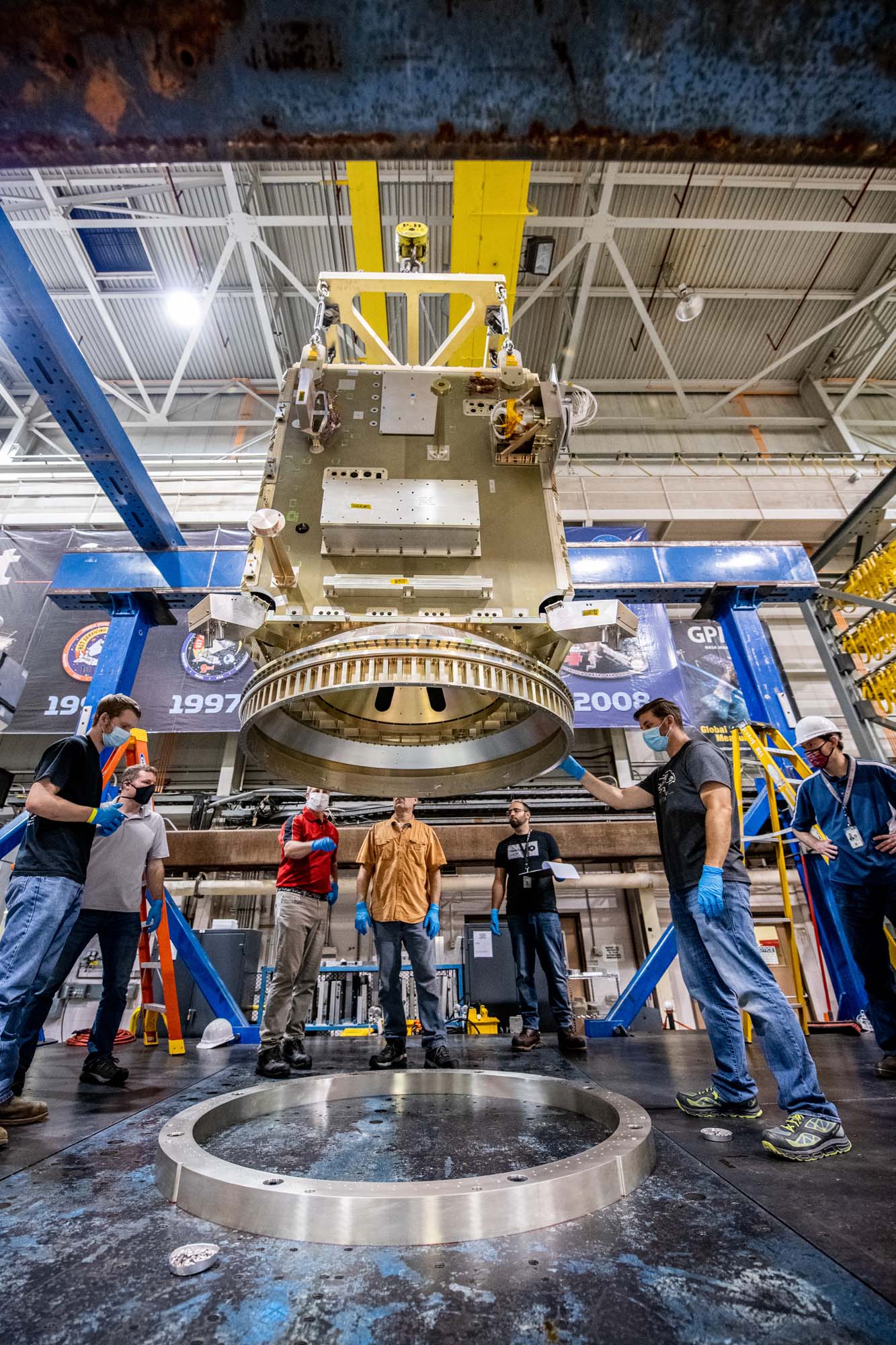
Assembling PACE spacecraft bus (+Z and -Z panels) using keel lift. Credit: Henry, Dennis (Denny)
Installing the passive ring and propulsion module onto the PACE observatory dolly. Credit: Henry, Dennis (Denny)
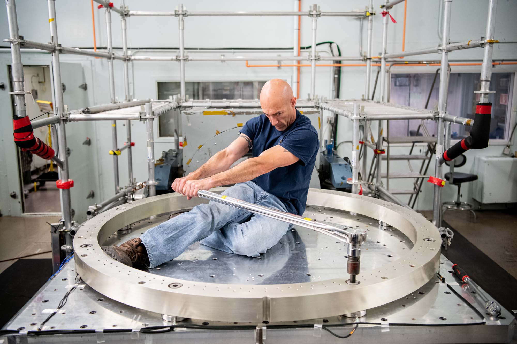
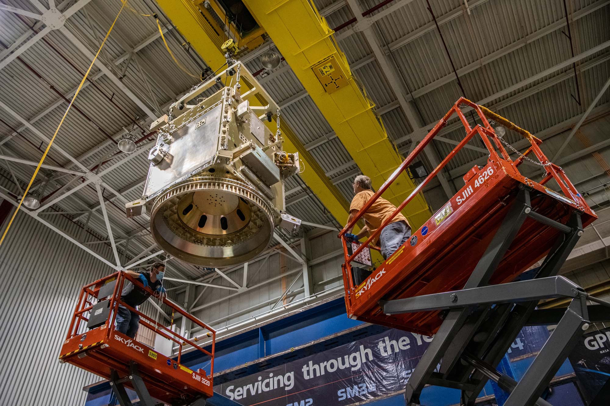
Lifting points proof test for spacecraft transport between facilities. Credit: Henry, Dennis (Denny)
PACE assembly for structural testing. Credit: Henry, Dennis (Denny)
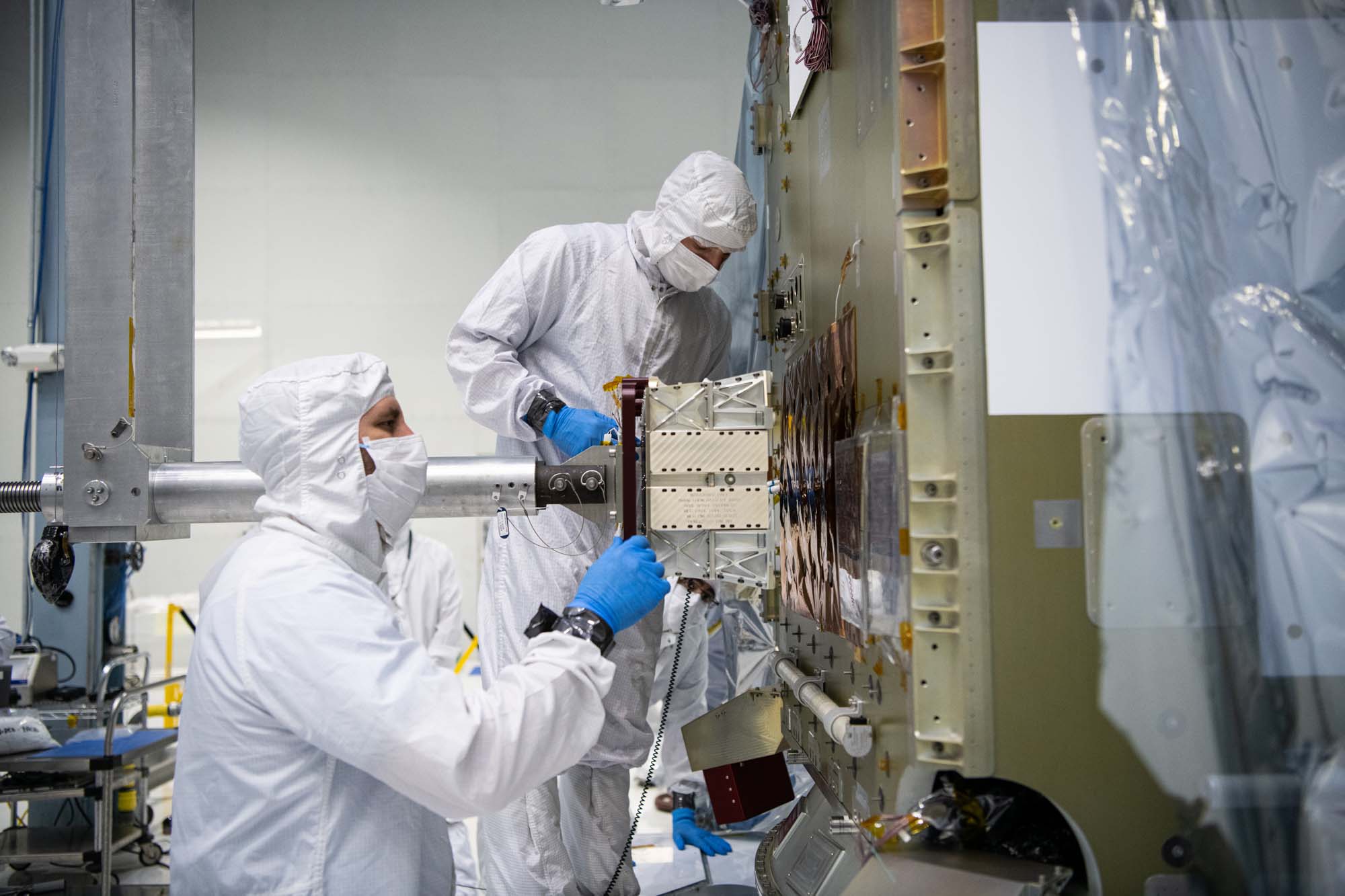
Installing torque circular connectors during panel integration. Credit: Henry, Dennis (Denny)
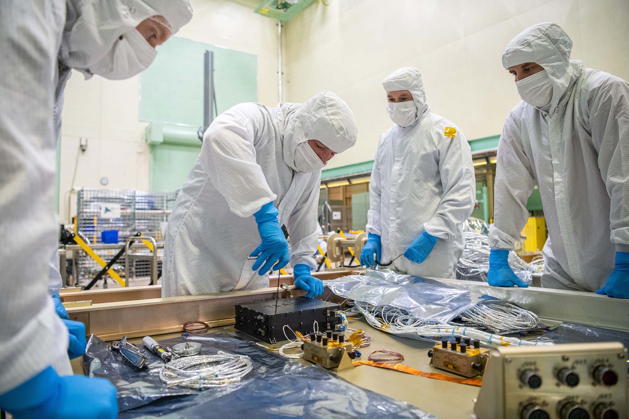
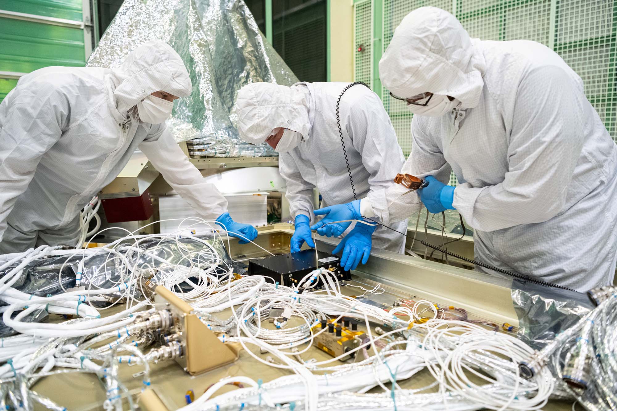
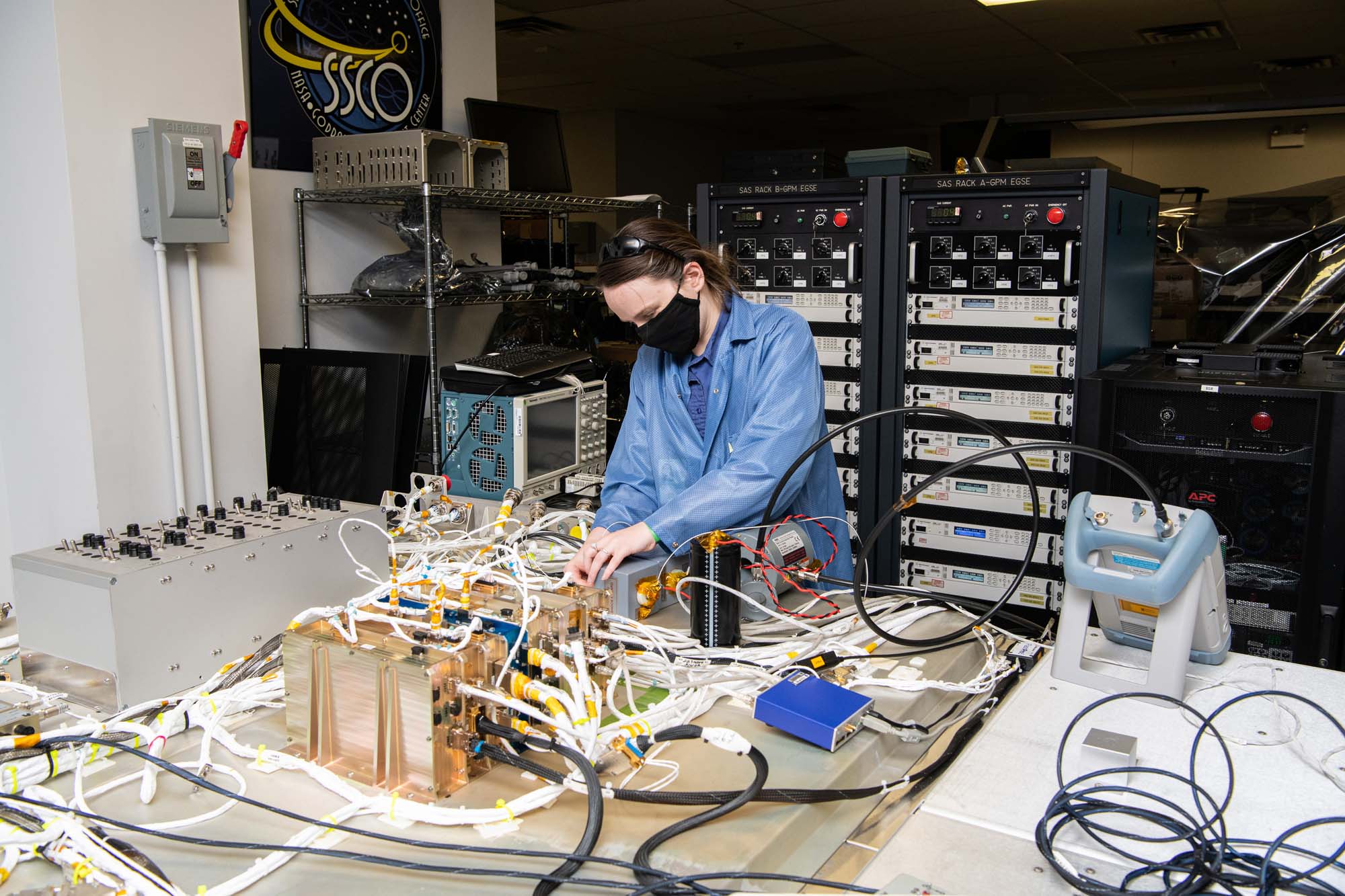
Performing electrical integration of engineering test unit's Ka-band transmitter. Credit: Henry, Dennis (Denny)
Electrical integration of engineering's test unit Ka-band transmitter. Credit: Henry, Dennis (Denny)

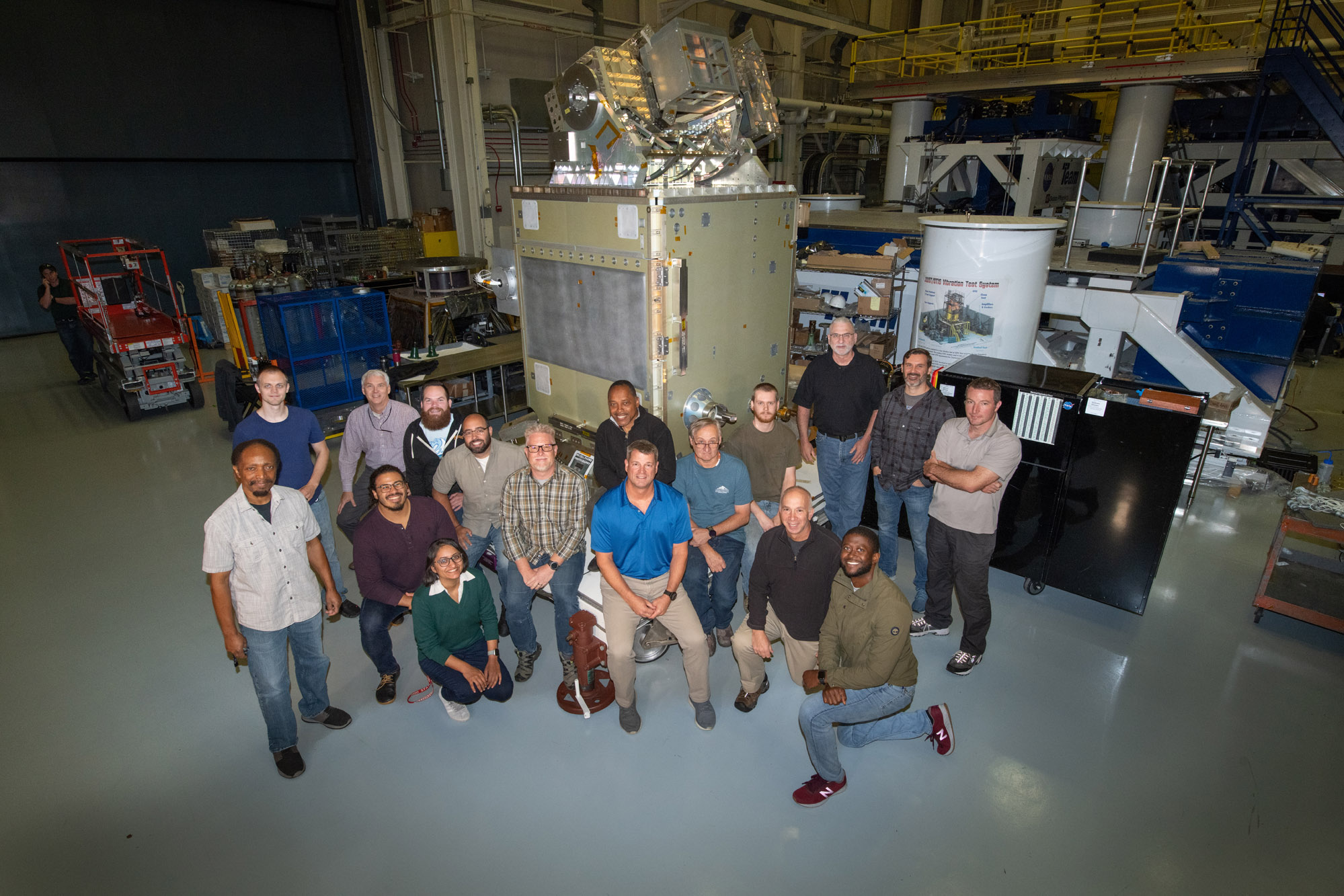
PACE Team / Group photo December 2021. Credit: NASA
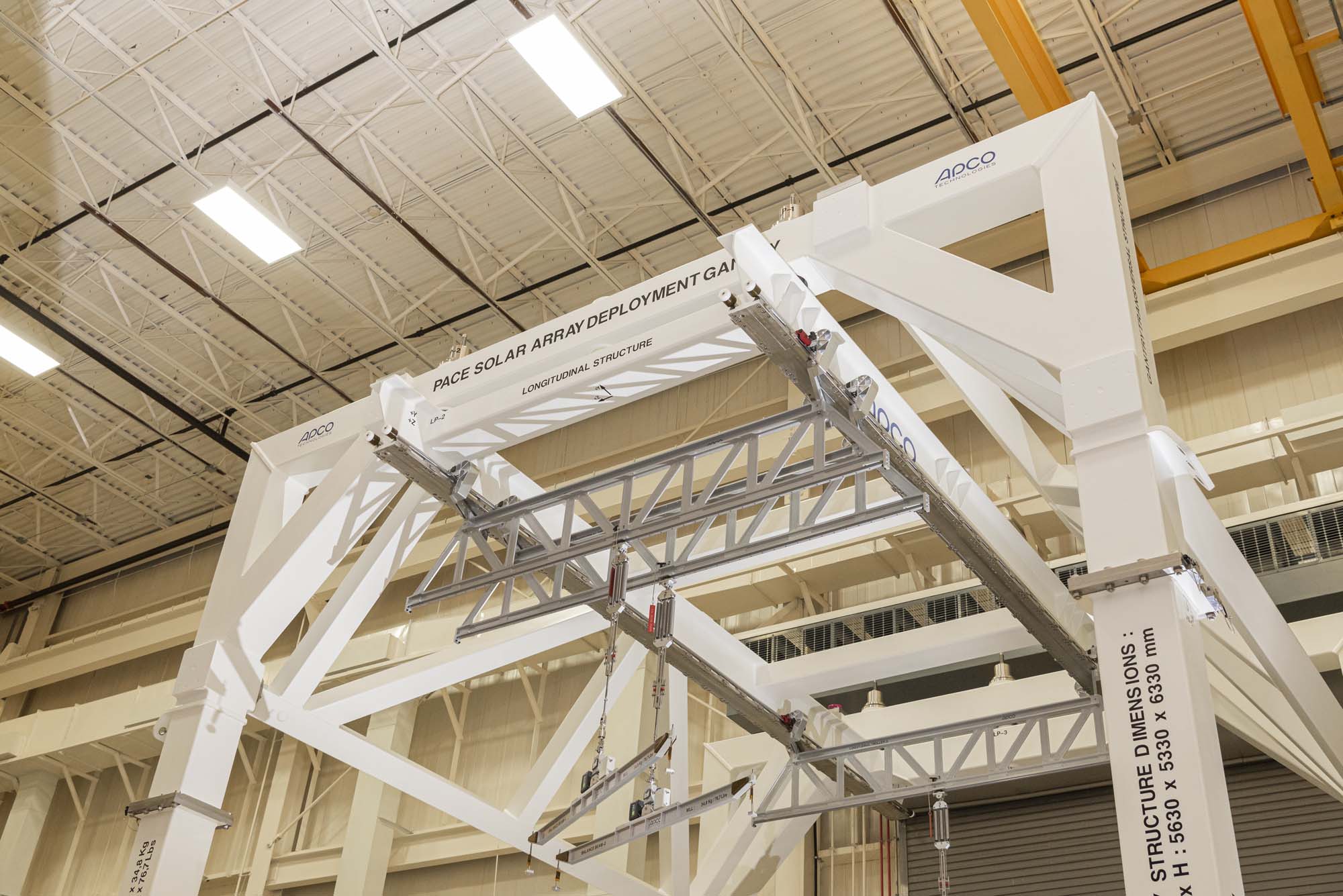
PACE solar array deployment gantry. Credit: Guinto, Michael
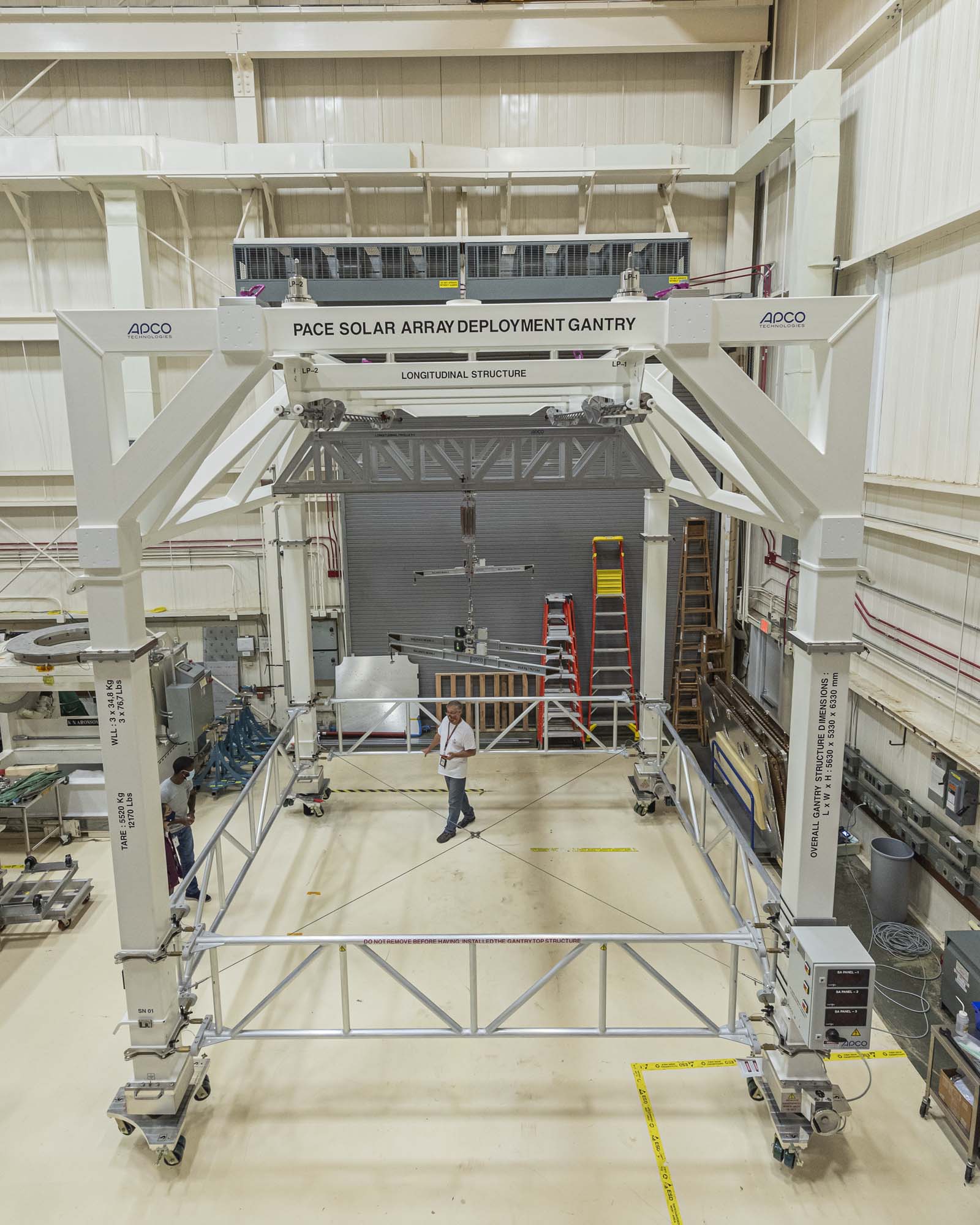
PACE solar array deployment gantry. Credit: Guinto, Michael
Installing tilt and solar array drive electronics to a PACE spacecraft panel (-Y). Credit: Henry, Dennis (Denny)
Installing GPS receiver box to a PACE spacecraft panel (-Z). Credit: Henry, Dennis (Denny)
Installing stimulators on PACE course sun sensors. Credit: Henry, Dennis (Denny)
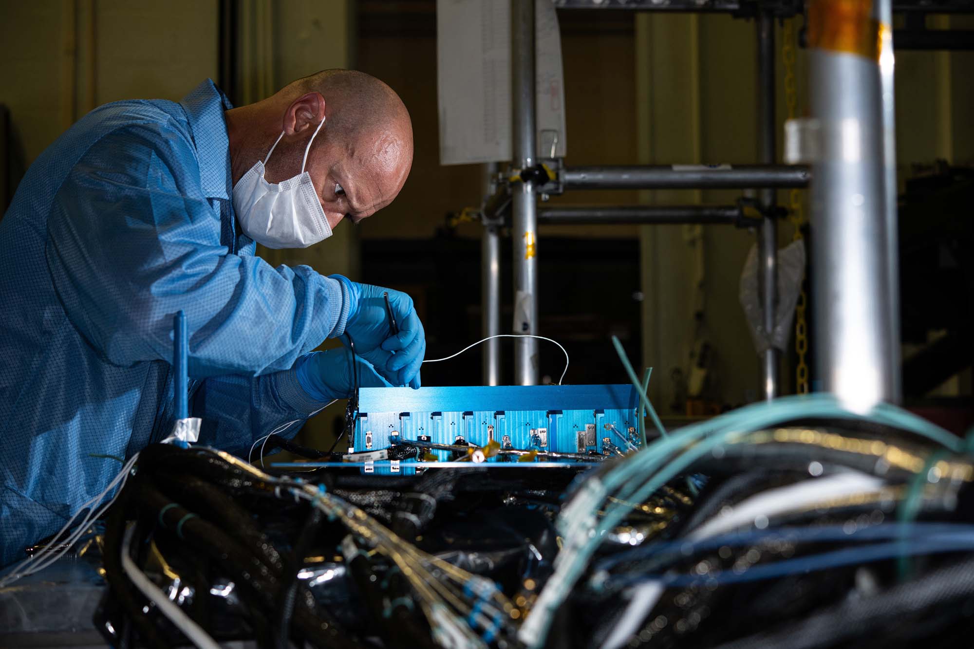
Performing electrical integration of flight power system electronics and attitude control electronics box. Credit: Henry, Dennis (Denny)
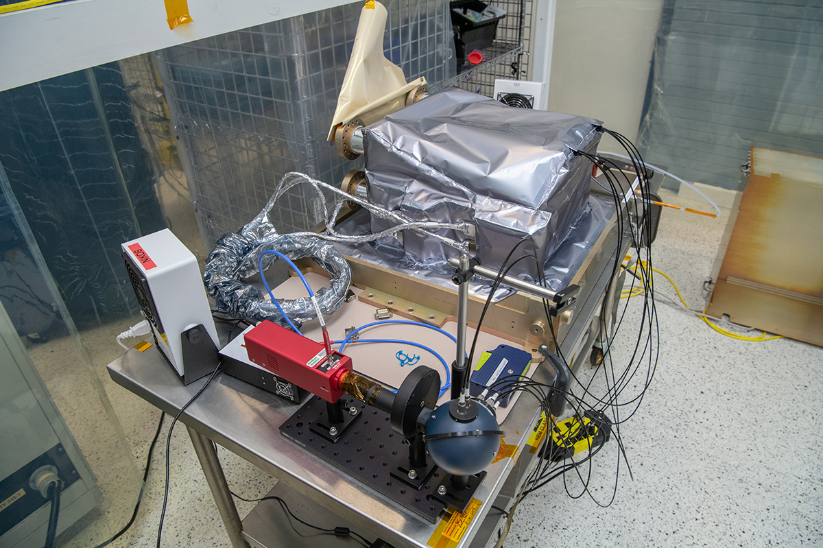
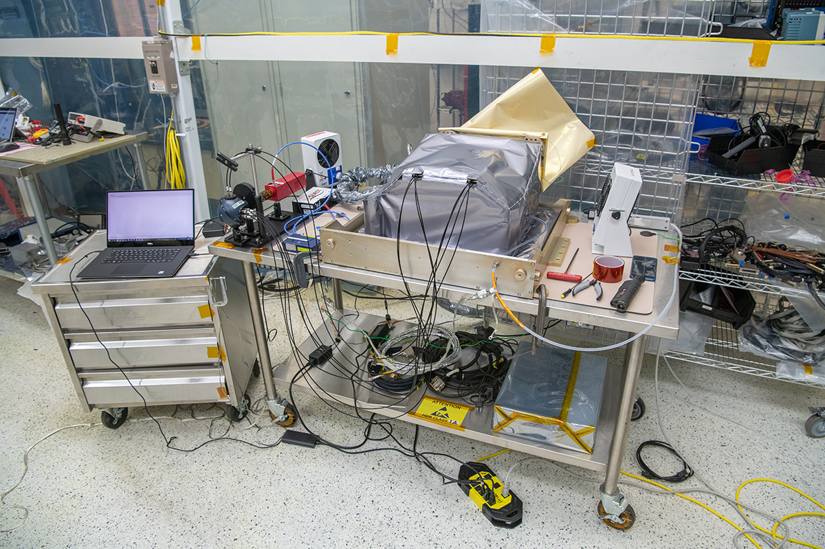
Lift fixture within thermal vacuum chamber. Credit: Seixal, John
Installed multilayer insulation thermal blankets on PACE propulsion module. Credit: Lambert, Barbara
Qualification of the spacecraft bus structure strength. Credit: Henry, Dennis (Denny)
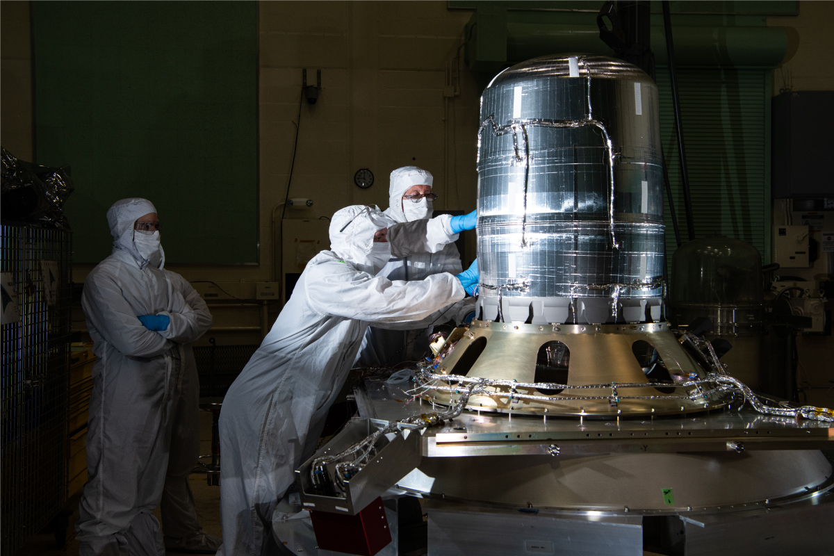
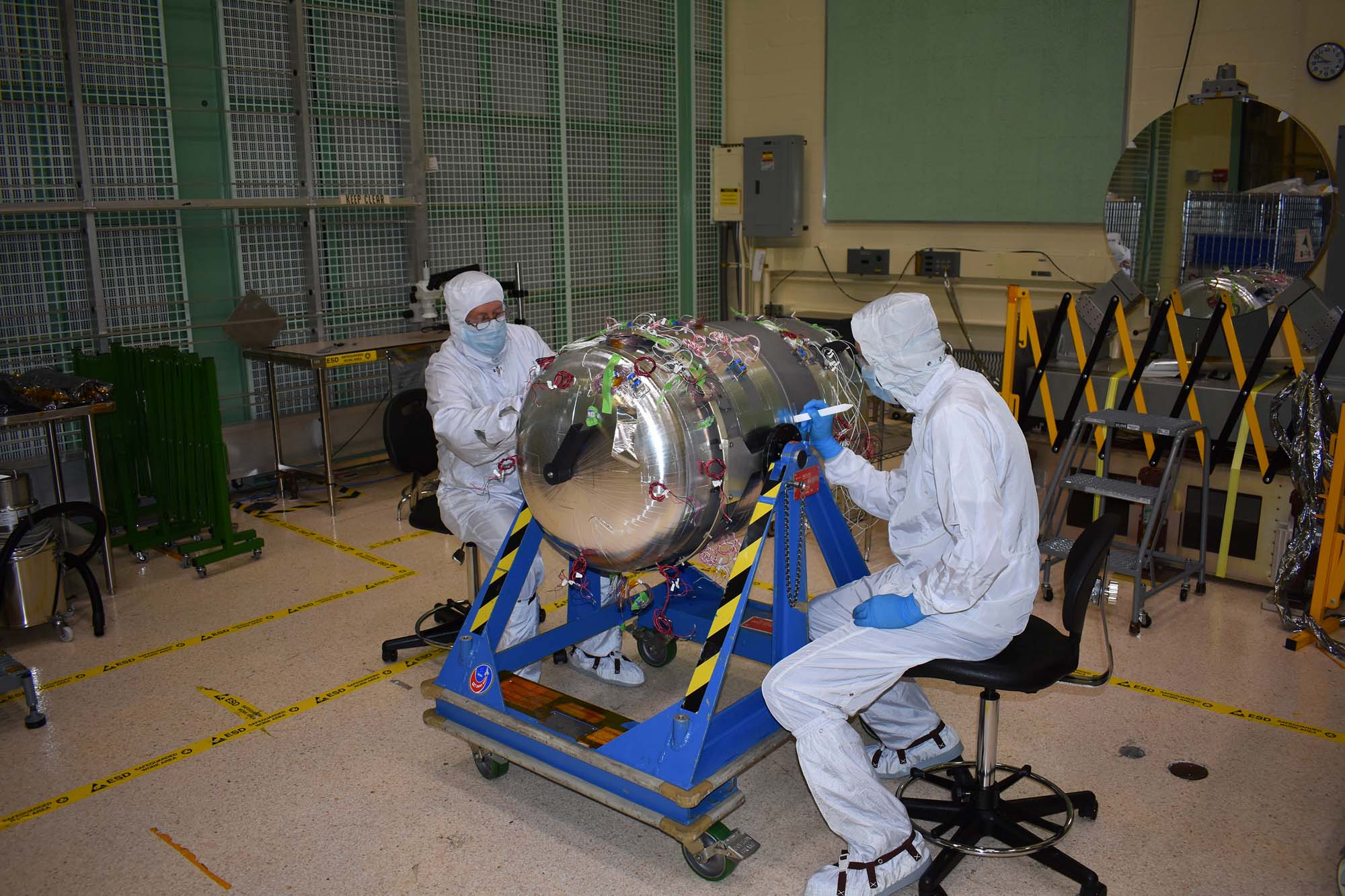
Installing the flight propellant tank into the frustum. Credit: Dennis Henry
Assembling the structure, installing the mass simulators and tilt platform/solar array strength test fixtures, and assessing and demonstrating the panel G-Negation system functionality. Credit: Dennis Henry
Inspecting attitude control electronics box telemetry for fluctuations registered during testing. Credit: Henry, Dennis (Denny)
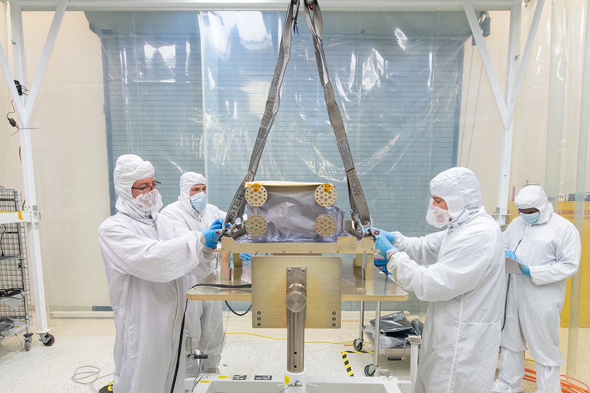
Testing observatory lifting points and pull strength of tilt platform, solar array, SPEXone, HARP2, and bus star tracker interfaces. Credit: Henry, Dennis (Denny)
Lift of PACE spacecraft into the testing modal facility. Credit: Henry, Dennis (Denny)
Spacecraft structure with mass simulators, tilt platform & solar array strength test fixtures. Credit: Henry, Dennis (Denny)
Mass simulation assembly structure. Install of tilt platform/solar array strength test fixtures.
Credit: Henry, Dennis (Denny)
Thermal integration of PACE propulsion tank.
Inertial reference unit electromagnetic interference testing procedure. Credit: Henry, Dennis (Denny)
Installing the ETU SDA onto the Turnover Dolly.
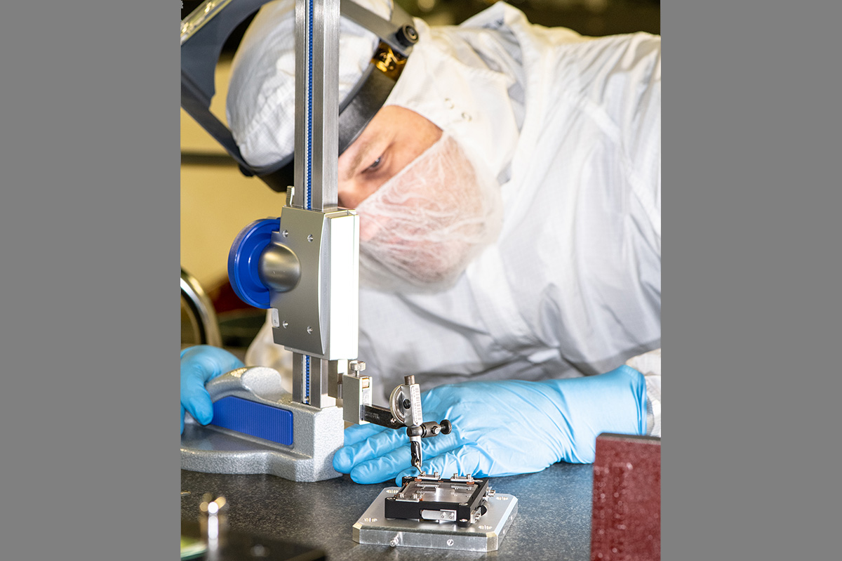
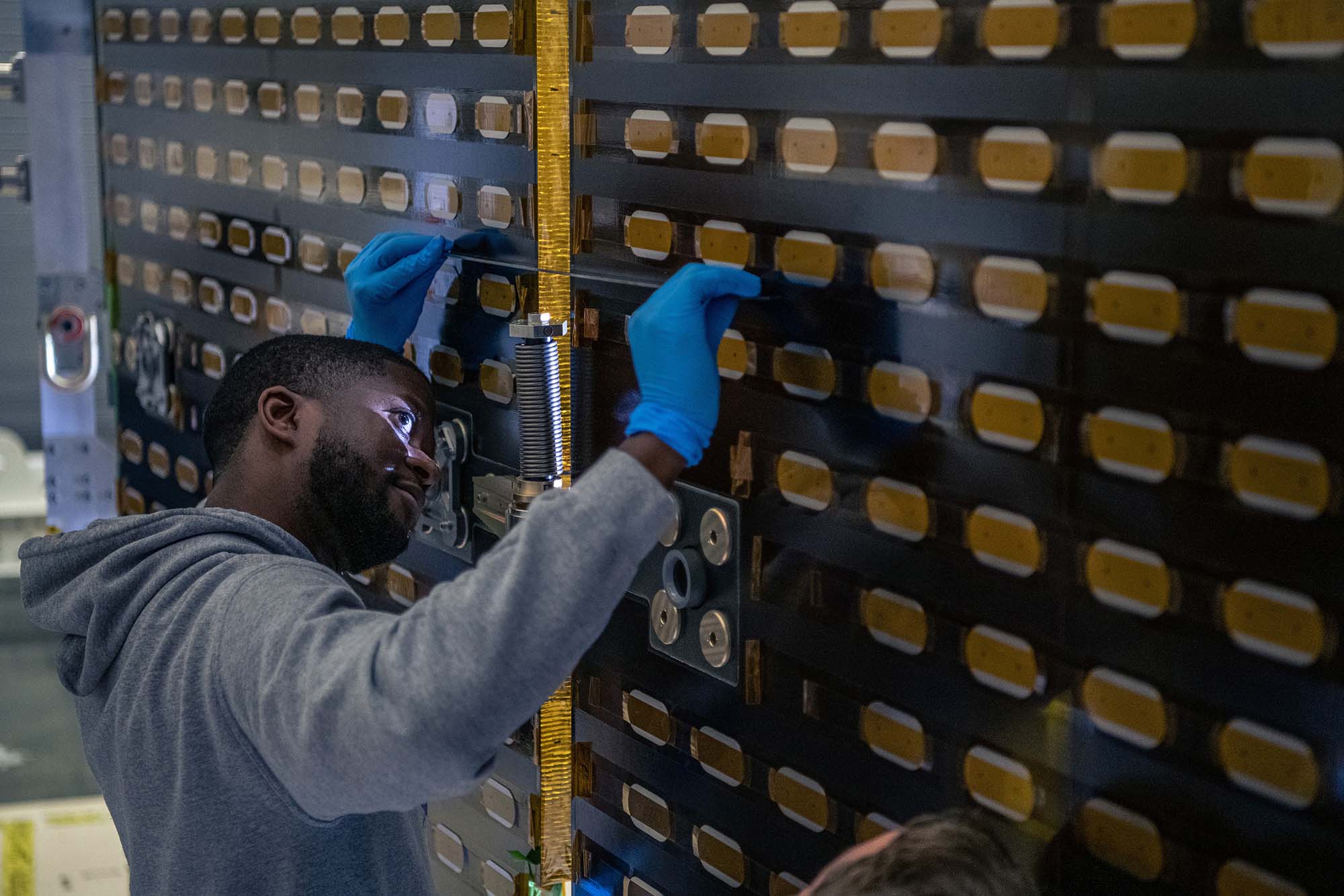
NASA Technician Andrew Scharmann verifies correct spring deflection to properly preload the depolarizer optic into the Flight Depolarizer Mount Assembly.
ETU SDA Post Delivery Acceptance Testing side view.
ETU SDA Post Delivery Acceptance Testing front view.
ETU SDA in its shipping container for post delivery to Goddard Space Flight Center.
Click image to view slideshow.